Contactor panel – Hired-Hand ICS-500 Environmental Controller User Manual
Page 19
Integrated Control System 500 17
6.3. Contactor Panel
6.3.1. General Description
Hired Hand’s Contactor Control System is a pre-wired set of heavy contactors designed
to allow automatic switching of large loads. (Up to 2 Hp per stage.)
6.3.2. Terminal Locations/Types
Along the left hand side on the inside of the contactor panel are two long terminal
strips, each section of strip is labeled with stage number, line in, and line out. Be sure to
connect each wire carefully to prevent line crossing.
6.3.3. Controls
6.3.3.1. Inside Controls
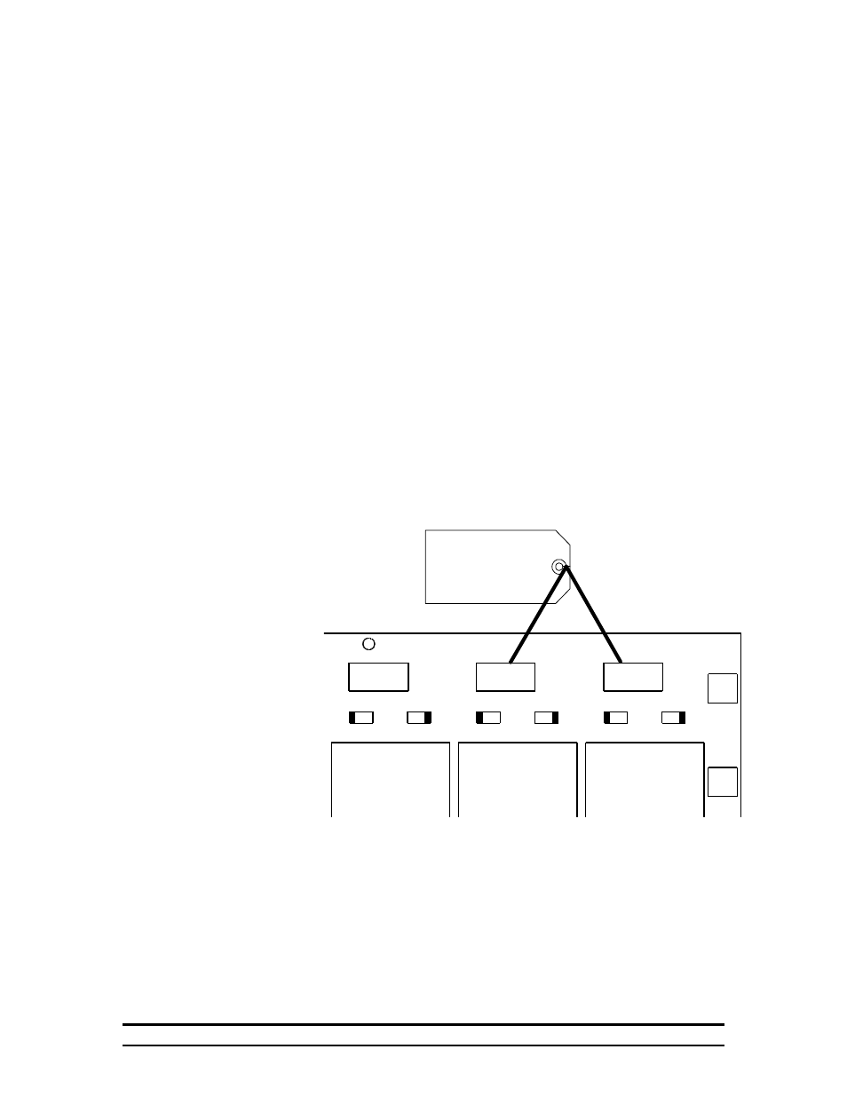
There are eight switches on the inside of your ICS-500. Looking into
the box they will be on the extreme right hand side on the boards with
the large black relays. Each switch has two positions: Heat, and Cool.
It is important that the switch be in the right position according to the
equipment on that particular stage. (If you have fans on a stage, that
stage’s switch should be in the cool position.)
The position of the switch determines whether the stage is turned on if
temperature reaches the high or low limit. Obviously it is important
for heaters to not turn on when temperature is dangerously high.
J4
J5
VR4
H
E
A
T
CR4
SW4
C
O
O
L
VR3
H
E
A
T
CR3
SW3
C
O
O
L
VR2
H
E
A
T
CR2
SW2
C
O
O
L
RLY4
RLY3
RLY2
COOL
HEAT
August 26, 1991 L.Self
Copyright C 1991,1992
PCB 115 (REV 0)
These switches
must be in the
proper position.
6.3.3.2. Front Panel
The only controls on the outside of the contactor panel are the
“Auto/Off/On” toggle switches. These switch positions allow you to
select whether the stage will be on continuously, be turned on or off as
needed by the controller, or turned off unless needed by the back-up
system. An indicator light is provided for each stage to show at a
glance which stages are running.