Installer, F/n: lltb004, Keep cover in place. remove for service only – Hired-Hand Universal Ray Tube Heaters: AG2 Series Rev.10-08 User Manual
Page 4: Caution
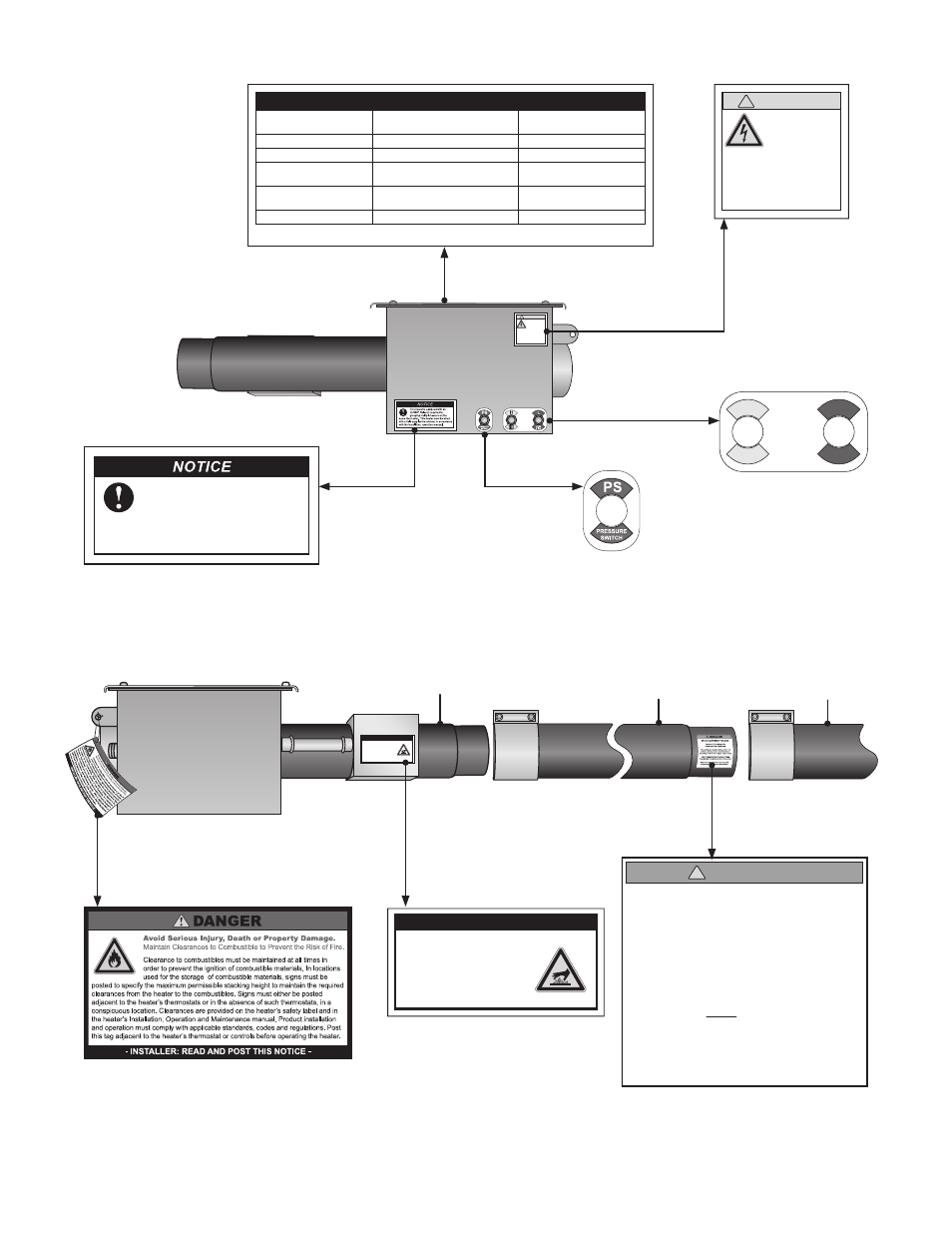
!
CAUTION
Provide 24
Volts Only
This heater has a 24 Volt
control system. Do not
connect 120 Volt power
supply, as it will damage
the controls.
LED CODE
FAULT STATUS
FAULT CODE DELAY
Initial flash on power up,
then steady off
No fault, normal operation
No delay
Steady on
Module failure / Internal fault
No delay
1 flash
Ignition failure
3 minutes
2 flashes
APS air flow fault
NOTE: fan/intake/exhaust
1-30 seconds
4 flashes
Erroneous flame signal
No delay
No flash on 117V start-up
Transformer fault
No delay
NOTE: Lockout LED CODE appears on completion of the soft lockout operation.
This heater is equipped with an
HLRB/P Relay(s) required for
grouping multiple heaters on the
same thermostat. This heater must be wired
with a field supplied transformer in accordance
with the installation, operation manual.
AVOID EQUIPMENT FAILURE
THIS 10 FT. TUBE IS THE
COMBUSTION CHAMBER.
THIS TUBE MUST BE THE FIRST TUBE
FOLLOWING THE BURNER CONTROL BOX.
!
INSTALLER
The combustion chamber utilizes either 409
stainless, titanium alloy or aluminized steel -
depending on the model number of your heater.
Rotate the tube’s welded seam to bottom.
Consult the manual(s) for further details.
4
1.0
Safety • Safety Labels and Locations • Clearance to Combustibles
F/N: LLTB031
Affixed on models with relay(s) installed
AG2
Series
F/N: LLTB007(3)
Located in control box
F/N: LLDR003
Affixed on models
with relays installed.
SERVICE ACCESS PANEL
IGNITER & FLAME SENSE COMPARTMENT
1. Turn off gas & electricity.
2. Remove cover by lifting top
cover upward and outward.
CAUTION:
HOT SURFACE.
KEEP COVER IN PLACE. REMOVE FOR SERVICE ONLY.
SERVICE ACCESS PANEL
IGNITER & FLAME SENSE COMPARTMENT
1. Turn off gas & electricity.
2. Remove cover by lifting top
cover upward and outward.
CAUTION: HOT SURFACE.
KEEP COVER IN PLACE. REMOVE FOR SERVICE ONLY.
F/N: LLTB004
(orange)
F/N: LLTB026
Right Panel
(Valve Compartment)
Radiant
Tube
Primary Combustion
Chamber(s)
16” Burner Tube
Left Panel
(Fan Compartment)
!
CAUTION
Provide 24
Volts Only
This heater has a 24 Volt
control system. Do not
connect 120 Volt power
supply, as it will damage
the controls.
F/N: LL01 - Clearance Safety Tag
(Affix adjacent to heater’s control)
HIGH
FIRE
H
L
LOW
FIRE
F/N: LLV2EP9
F/N: LLV2EP15