Notice – Hired-Hand Universal Ray Tube Heaters: AG2 Series Rev.10-08 User Manual
Page 15
NOTICE
Bypassing any switch is intended for testing purposes only. Do not leave switch bypassed
during normal operation or the heater’s built-in safety mechanisms will be compromised.
15
4.0
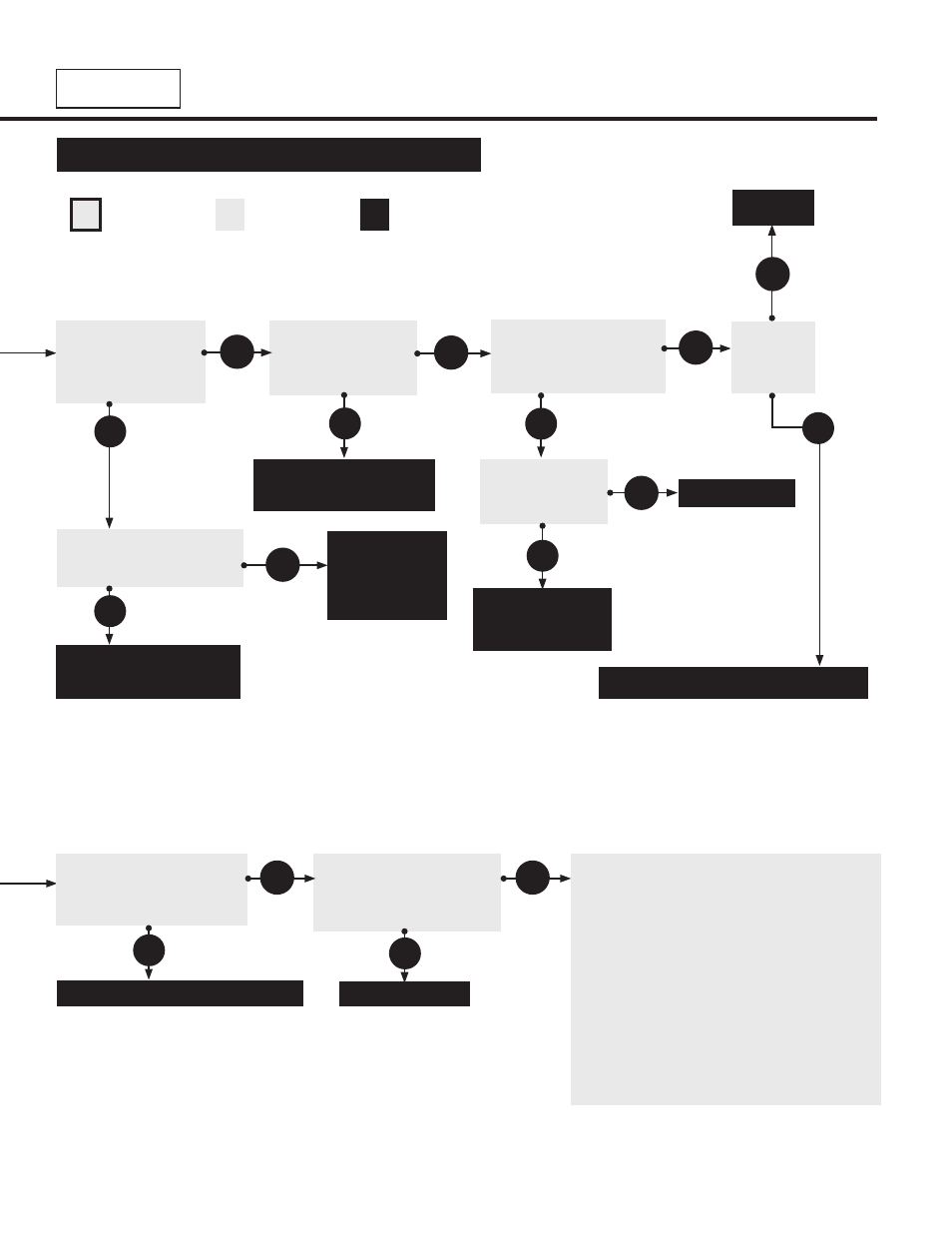
Troubleshooting Guide
Key
Start
Question
Process
Question
Corrective
Action
AG2
Series
*Refer to LED diagnostic Fault Code Chart; p.13.
Is the power across
the 24V terminal and
ground on the
circuit board 24V?
Check circuit board
for flashing fault code
(p.13) Is the circuit board
sending 120V to the fan?
Is the fan
obstructed?
Remove
obstruction.
Is the pressure
switch stuck in the
closed position?
Replace switch.
Yes
Yes
Is there 120V on the
primary side of the
internal transformer?
The low fire relay is faulty
and must be replaced.
The circuit board is
faulty and must be
replaced.
Repair wiring between
power in and transformer.
The fan is faulty and must be replaced.
The internal
transformer is
faulty and must
be replaced.
Is the power across
the TH terminal and
ground on the circuit
board 24V?
Yes
No
No
Yes
Yes
No
No
Yes
Check for loose wiring or
restrictions in hose connec-
tions to pressure switch.
Are they OK?
Replace wiring or hose connections.
*After 1-30 seconds of
non-operation has passed,
is there a flash code for
APS fault (2 flashes)?
Replace the pressure switch after
verifying:
• Baffle(s) are in the radiant tube furthest
from the burner.
• Heater, fan blowers ,squirrel cage, intake
and exhaust are clean and free from dirt
and obstructions.
• The 4” air intake pipe does not exceed 20 ft.
and/or 2 elbows.
• There is not a negative pressure
experienced at the area of air intake (e.g.;
high winds, attic space, tightly sealed
building).
Consult factory.
No
Yes
No
No
No
Yes