Mega flow, Fan & cone installation, Detail g – Hired-Hand Mega Flow SlantWall Fans: 36 48 & 52 Mega Flow Cone Fan Unassembled User Manual
Page 8: Detail i
Part No. 4801-3006 Rev 6/07
36" 48" & 52" Mega Flow - Unassembled
Page 8 of 12
MEGA FLOW
Fan & Cone Installation
SLANTWALL
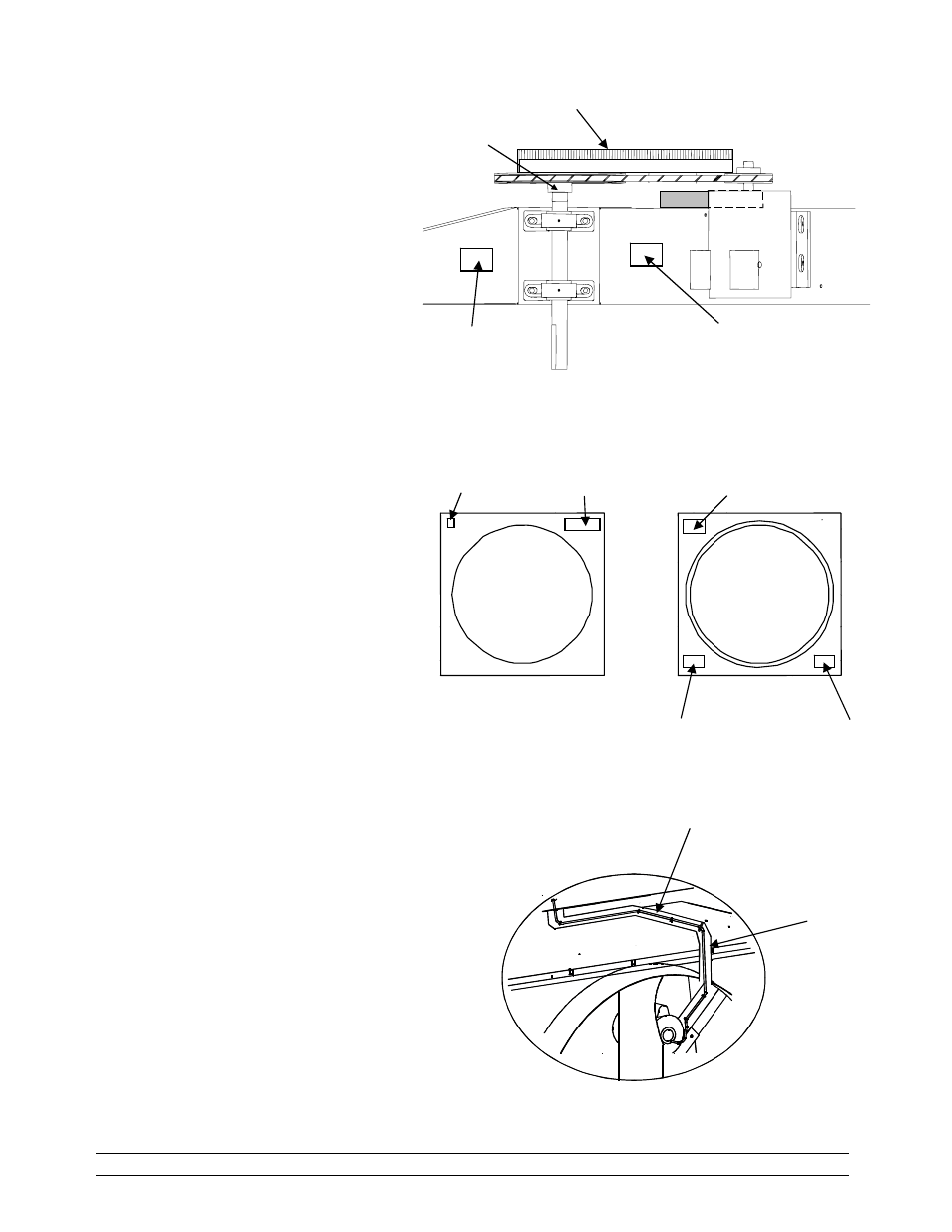
Detail G
Straight edge
Prop pulley
1011-5000
14.
Refer to Figure 2. Install
the key shear (1019-2417)
onto the prop shaft. Slide
the prop onto the shaft until
the end of the shaft is flush
with the prop hub. Use a 12
point socket to tighten the
prop set screw.
Recommended torque of set
screw is 100 in. lbs. min.
15.
Carefully lay cabinet flat
with prop side down.
Slowly rotate blade.
Observe that blade is equal
distance from orifice throat
at all points of rotation.
Shift X-brace as required to
center prop.
16
After prop alignment,
FIRMLY TIGHTEN ALL
BOLTS HOLDING X-
BRACE TO CABINET.
17.
Refer to Detail G. Use a
straight edge to align
pulleys as shown. Securely
tighten set screw of motor
pulley and prop pulley.
Recommended torque is
110 in. lbs. min. Install belt
(1022-3102) onto motor
pulley, tension pulley, and
prop pulley. See belt
installation sheet.
18.
Refer to Details G and H.
Carefully raise fan to
upright position. Affix
labels to cabinet and brace
as shown.
19.
Refer to Detail I. Route the power cord.
Use nylon ties to secure cord along route as
shown.
20.
Fan assembly complete. When attaching
cone, see Manual 4801-5128.
Power Cord
(Not Included
with 52
" Version)
Nylon Tie
(1007-5005)
Detail I
NOTE: In this view the Idler Pulley is directly under the
Motor pulley
.
Warning Hand
(4501-1116)
Danger Hand
(4501-2622)
Made in USA
(4501-2957)
Danger Head
(4501-2620)
FRONT
BACK
MEGAFLOW
(4501-6084)
Detail H
Fan Bearing
Maintenance
(4501-6128)
Fan Rotary
Tensioner
(4501-6129)