Hired-Hand Mega Flow SlantWall Fans: 36 48 & 52 Mega Flow Cone Fan Unassembled User Manual
Page 6
Part No. 4801-3006 Rev 6/07
36" 48" & 52" Mega Flow - Unassembled
Page 6 of 12
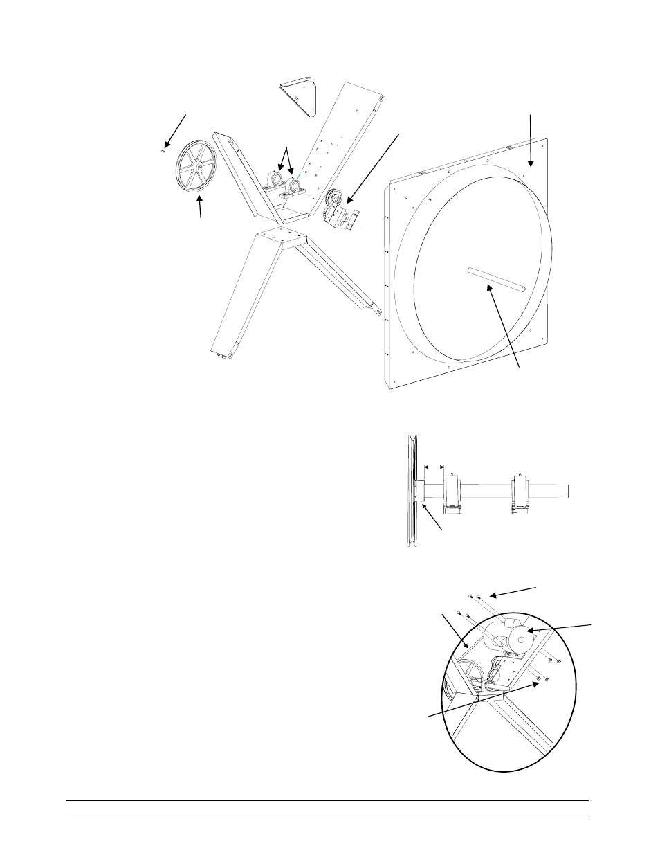
6. Refer to Figure 1 above. Insert the Key Shear
(1019-2417) into the Shaft (0411-4535). Slide Prop
Pulley onto shaft until Pulley is flush with the end of
the shaft.
MAKE SURE SET SCREW SIDE OF PULLEY IS
TOWARD SHAFT. Tighten set screws of Pulley.
Recommended torque is 100 in. lbs. min.
7. Insert shaft assembly into the bearing pillows as
shown in Detail D. Slide shaft assembly into
bearings to a distance of 1-3/16" (3.016 cm) between
the edge of the bearing pillow and the hub of pulley
as shown in Detail D. Tighten the lock screws on
the bearing pillows. Recommended torque of the
lock screws is 65 in. lbs. min, and 83 in. lbs. max.
8. Refer to Figure 1 above. Fasten flared orifice to the
top and bottom brace assembly with four 5/16" CAP
screws (1004-1414), flat washers (1003-0103), and
lock nuts (1001-1735).
9. Refer to Detail E. Install the motor using 5/16" bolts
(1002-2373) and lock nuts (1001-1735).
Shaft
Bottom Brace )
Bearing Pillow
(1016-0100)
Top Brace
Prop Pulley 36" (1011-5002)
48"&52" (1011-5000)
Idler Pulley Assy
(6403-9201)
Flared Orifice
36" (0404-2100)
48" (0404-4250)
52" (0404-5714)
Rear Gusset
(0404-2913)
Key Shear
(1019-2417)
Figure 1 – Assemble Brace, Gusset, Bearings and Orifice
Detail E
Lock Nut
5/16
"-18
(1001-1735)
Bolt 5/16
"-18 x ¾"
(1002-2373)
Belt
36"&48" (1022-3105)
52" (1022-3102)
1-3/16"
3.016 cm
Detail D
Set screw
Side of Pulley.
Motor