Fan assembly instructions – Hired-Hand Mega Flow SlantWall Fans: 36 48 & 52 Mega Flow Cone Fan Unassembled User Manual
Page 5
Part No. 4801-3006 Rev 6/07
36" 48" & 52" Mega Flow - Unassembled
Page 5 of 12
5. Fan
Assembly
Instructions
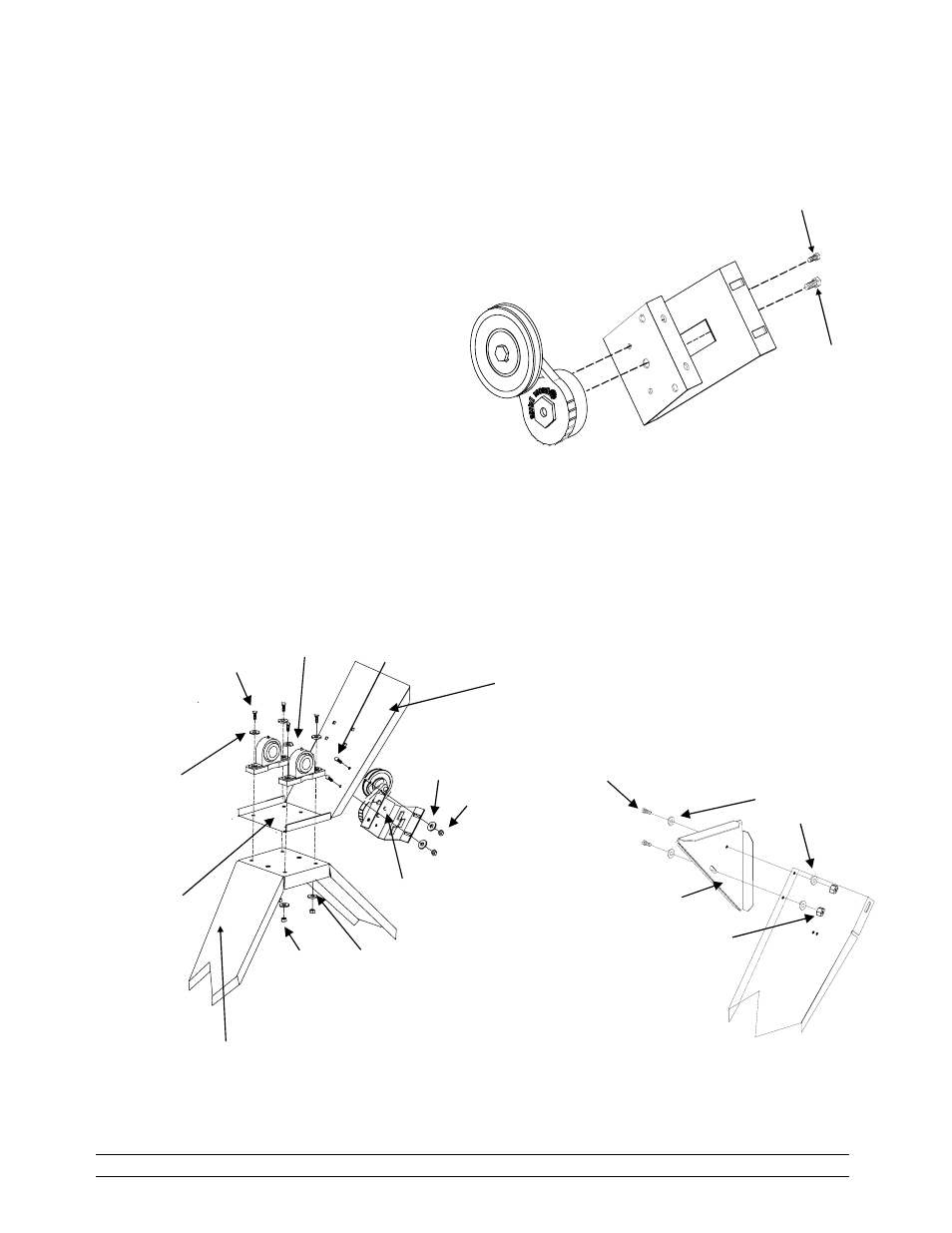
1. Refer to Detail A and assemble the Sheave
Idler Pulley (1011-9005) to the Belt Tension
Bracket (0404-4665) with Cap Screw (1004-
1426) and Screw (1004-6020) as shown. Set
the assembly aside until Step 4.
2. Refer to Detail B. Place Top Brace on top
of the Bottom Brace and align holes.
3. Place the two Bearing Pillows (1016-
0100) on the Top Brace and bolt with
3/8” cap screw (1004-3054), flat washers
(1003-1462) and lock nuts (1001-1457).
Tighten securely.
4. Install the idler pulley assembly prepared in Step
1.
5. Install the gusset to the top corner of the Top
Brace as shown in Detail C.
CAP Screw
5/16-18 X 1
"
(1004-1414)
Flat Washer
5/16
" X ¾"
(1003-0103)
Lock Nut
5/15
"-18
(1001-1735)
Detail C
Motor Mount Gusset
36"&48" (0404-4649)
52" (0404-5624)
Lock Nut
¼
" x 20
(1001-1446)
Bearing Pillow
(1016-0100)
Cap Screw
3/8
" X 16 X 1 ½"
(1004-3054)
Idler Pulley
Assembly
(6403-9201)
Flat Washer
3/8
" X 1 O.D
(1003-1462)
Flat Washer
3/8
" X 1
Lock Nut
3/8
" x 1O.D.
(1001-1457)
Detail B
CAP Screw
¼
" X 20 X ¾"
(1004-1402)
Flat Washer
¼
" USS
(1003-1461)
Side of brace
not shown for
clarity.
Top Brace 36" (0404-4794)
48"&52" (0404-4648)
Bottom Brace 36" (0404-4793)
48"&52" (0404-4647)
Idler Pulley
(1011-9005)
Belt Tension
Bracket
(0404-4665)
Detail A
Screw ¼
" - 20 X 3/8"
(1004-6020)
Cap Screw
3/8
" – 16 X 1"
(1004-1426)