Typical installation, Step 2 pump location (general), Step 1 pre-installation check – Stuart Turner 3.2 bar PS User Manual
Page 2
- 2 -
TYPICAL INSTALLATION
The plumbing installation must
comply with the following:
The Water Supply (Water Fittings) Regulations 1999.
BS6700 and building regulations.
Be installed by a competent person.
If in doubt contact Stuart Turner Ltd
STEP 2 PUMP LOCATION (GENERAL)
WARNINGS:
The pump must not be located where the inlet pressure to the pump is
greater than permitted.
Care should be taken to protect pump from frost and freezing,
particularly when located in a loft installation.
Pump Location
If possible site the pump in a location where in the unlikely event of a
water leak, any spillage is contained or routed to avoid electrics or
areas sensitive to water damage.
The motor casing can become very hot under normal operating
conditions, care should be taken to ensure it cannot be touched
during
operation.
Ensure all components in the down-stream system to be pressurised
are suitably rated to accommodate the final system working pressure.
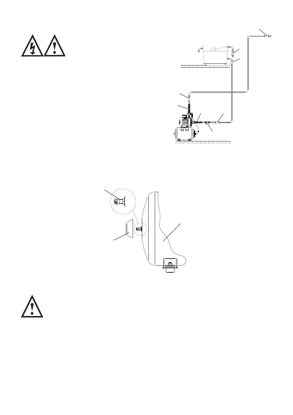
This diagram should be used for
schematic reference only
1: Isolating valve
2: Inlet strainer
3: Flexible hose
STEP 1 PRE-INSTALLATION CHECK
Your pump set comprises of two major parts, the main pump and pressure vessel. The
pressure vessel is pre-charged with air at the factory to 140 kPa (1.4 bar or 20.3 psi).
This pressure should be checked at the Schrader valve using a tyre pressure gauge and
adjusted if necessary using a car or bicycle pump prior to installation.
PUMPS
1
1
1
1
1
2
3
3
Fig. 1
Fig. 2
Pressure
Vessel
Schrader
valve
Plastic
Protector Cap
(unscrew to
access valve)