Setup, 1 setup procedure, Connection – Yokogawa JUXTA M Series Digital Limit Alarms MVTK User Manual
Page 9
<1. Setup >
1-1
IM 77J04J11-01E 1st Edition : 2006.08.25-00
1.
Setup
This chapter describes the setup procedure required to use the communication
functions (PC link, Ladder and MODBUS) and the communication parameters of the
M Series.
1.1
Setup Procedure
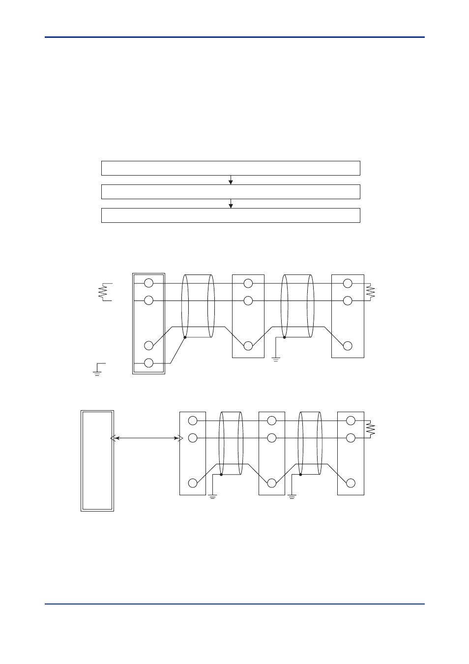
Set up the communication functions on the M Series as follows:
Set up the communication function parameters of the M Series. (See section 1.2.)
Connect a higher-level device and a M Series. (See the connection diagram below.)
Create communication programs for the higher-level device to perform communication.
Note: Refer to the documentation of each higher-level device when creating communication programs.
B (+)
A (-)
Shielded
B (+)
A (-)
B (+)
A (-)
M Series
M Series
PLC
JIS Class D grounding
(grounding resistance of 100
Ω
or less)
JIS Class D grounding
(grounding resistance of 100
Ω
or less)
Terminating resistor
220
Ω
1/4 W
Terminating resistor
220
Ω
1/4 W
• Connection
1
2
3
1
2
3
SG
COM
COM
B (+)
A (-)
B (+)
A (-)
B (+)
A (-)
M Series
M Series
PC or PLC
JIS Class D grounding
(grounding resistance
of 100
Ω
or less)
Terminating resistor
220
Ω
1/4 W
JIS Class D grounding
(grounding resistance
of 100
Ω
or less)
1
2
3
1
2
3
COM
COM
ML2
(RS-232C/RS-485 converter)
RS-232C
(straight cable)
4
3
5
SG