Function, Command/response (for normal operation), Example – Yokogawa JUXTA M Series Digital Limit Alarms MVTK User Manual
Page 22
3-8
<3. PC Link Communication >
IM 77J04J11-01E 1st Edition : 2006.08.25-00
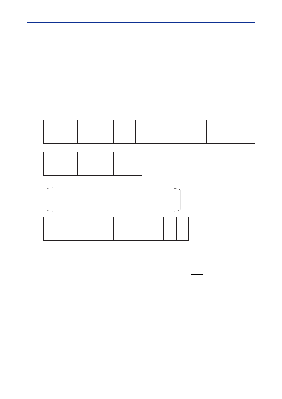
BWR Writes data into I relays on a bit-by-bit basis
●
Function
Writes ON/OFF data into a sequence of contiguous I relays by the specified number of bits,
starting at a specified I relay number.
•
The number of bits to be written into at a time is 1 to 256.
•
For the format of response in the event of failure, see subsection 3.1.2.
•
The command shown below includes the checksum function.
When performing communication without checksum, do not include the 2-byte
checksum element in the command.
●
Command/Response (for normal operation)
Command
element
STX
Address
number
(ADR)
CPU
number
01
0
BWR
d1
d2
I relay
number
Comma
or space
Number
of bits
(n)
Comma
or space
• • •
dn
Checksum
ETX
Write data 0 and 1 indicate OFF and ON respectively.
Command (continued)
• • •
1
2
1
CR
1
OK
ETX
CR
Response
element
STX
Address
number
(ADR)
CPU
number
01
Checksum
Number of Bytes
1
2
2
2
2
1
1
Number of Bytes
1
2
2
1
3
5
1
3
2
1
1
dn: write data of the specified number of bits (n=1 to 256)
dn=0 (OFF)
dn=1 (ON)
●
Example:
Setting the user-defined flag of the M Series with address number 01 to ON.
The following command writes ON into the user-defined flag (I0033) of address number 01.
[Command]
[STX]01010BWRI0033,001,106[ETX][CR]
Note: The user-defined flags are flags that the user can freely read/write.
OK is returned in response to the above command.
[Response]
[STX]0101OK5C[ETX][CR]