Function, Command/response (for normal operation), Example – Yokogawa JUXTA M Series Digital Limit Alarms MVTK User Manual
Page 30
3-16
<3. PC Link Communication >
IM 77J04J11-01E 1st Edition : 2006.08.25-00
WRW Writes data into D registers and I relays on a word-by-word basis in
random order
●
Function
Writes register data specified for each register into the registers specified in random order
by the specified number of words.
•
The number of words to be written into at a time is 1 to 32.
•
For the format of response in the event of failure, see subsection 3.1.2.
•
The command shown below includes the checksum function.
When performing communication without checksum, do not include the 2-byte
checksum element in the command.
●
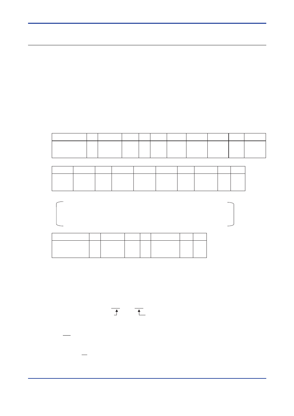
Command/Response (for normal operation)
Number of Bytes
1
2
2
1
3
2
5
1
4
1
Command
element
STX
Address
number
(ADR)
CPU
number
01
0
WRW
dddd1
Number
of words
(n)
Register
number 1
Comma
or space
Comma
or space
• • •
Checksum
dddd2
ETX
CR
• • •
4
Register
number 2
Comma
or space
5
1
ddddn
4
2
Register
number n
Comma
or space
5
1
1
1
Number of Bytes
1
2
2
2
2
1
1
Response
element
STX
Address
number
(ADR)
CPU
number
01
OK
CR
Checksum
ETX
Write data is specified in a 4-digit character string (0000 to FFFF) in hexadecimal.
Command (continued)
ddddn: write data of the specified number of words
ddddn is a character string in hexadecimal.
n=1 to 32
●
Example:
Writing 20.0 and 15.0 into the alarm-1 setpoint (D0101) and alarm-2 setpoint (D0102) of the M
Series with address number 10 respectively.
[Command]
[STX]10010WRW02D0101,00C8,D0102,00968F[ETX][CR]
200 in decimal
(Alarm-1 setpoint is 20.0.)
150 in decimal
(Alarm-2 setpoint is 150.0.)
OK is returned in response to the above command.
[Response]
[STX]1001OK5C[ETX][CR]