3 writing parameters, Command/response, Example – Yokogawa JUXTA M Series Digital Limit Alarms MVTK User Manual
Page 44
4-4
<4. Ladder Communication >
IM 77J04J11-01E 1st Edition : 2006.08.25-00
4.2.3
Writing Parameters
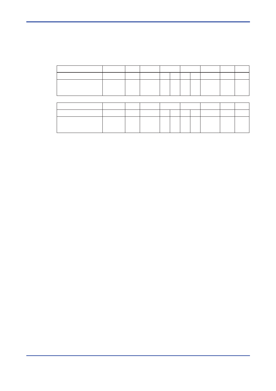
Shown below are the configurations of commands and responses when the parameters
are written into the M Series from the PLC.
●
Command/Response
Number of Bytes
1
1
2
2
1
1
1
1
Number of BCD Digits
2
2
1
4
4
2
2
1
1
1
Command element
Address
number
(ADR)
Parameter
number
CPU
number
01
CR
(0D)
LF
(0A)
0
1
+/-
0
dddd
Number of Bytes
1
1
2
2
1
1
1
1
Number of BCD Digits
2
2
1
4
4
2
2
1
1
1
Response element
Address
number
(ADR)
Parameter
number
CPU
number
01
CR
(0D)
LF
(0A)
0
1
+/-
0
dddd
●
Example:
Writing 200 into the alarm-1 setpoint (D0101) of the M Series with address number 01.
[Command]
01010101001002000D0A
The alarm-1 setpoint 200 (BCD code) is returned with respect to the above command (20.0
is expressed as 200).
[Response]
01010101001002000D0A