Modbus communication, 1 overview – Yokogawa JUXTA M Series Digital Limit Alarms MVTK User Manual
Page 47
<5. MODBUS Communication >
5-1
IM 77J04J11-01E 1st Edition : 2006.08.25-00
5.
MODBUS Communication
5.1
Overview
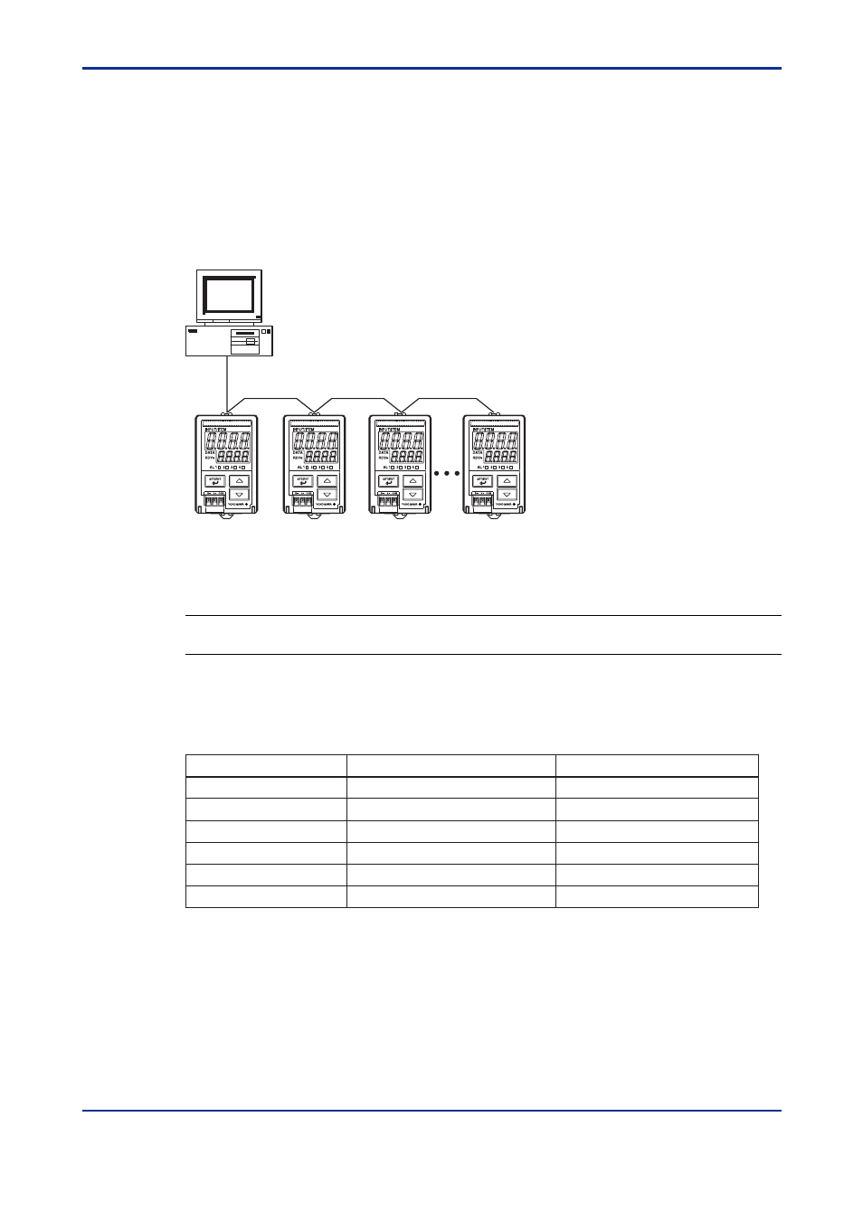
The use of MODBUS communication enables the M Series to communicate with a
PC. In this communication, you can use a PC to read/write data from/into D registers,
which are internal registers of the M Series.
PC
A maximum of 1200 m; up to 31 slave stations
Figure 5-1 Example of Connection for MODBUS Communication
Hereafter, PCs are generically called "higher-level devices."
See Also
Chapter 6 for information on the D registers.
For the MODBUS communication of the M Series, two transmission modes are supported:
ASCII mode and RTU mode (binary system).
Table 5-1
ASCII and RTU Modes
Item
ASCII Mode
RTU Mode
Number of data bits
7 bits (ASCII)
8 bits (binary)
: (colon)
Not necessary
Message end mark
Message start mark
CR+LF
Not necessary
Message length (*1)
Error detection
2N+1
N
Data time intervals
1 second or less
24 bit time or less (*2)
Longitudinal redundancy check: LRC Cyclic redundancy check: CRC-16
*1:
When the message length in the RTU mode is assumed to be "N."
*2:
When the baud rate is 9600 bps, 1
Ϭ
9600
ϫ
24 seconds or less applies.
In MODBUS communication, a higher-level device identifies each M Series with an ad-
dress number, which ranges from 01 to 99.