Functions and usage of d registers, 1 overview of d registers, 2 interpretation of d register map table – Yokogawa JUXTA M Series Digital Limit Alarms MVTK User Manual
Page 61
<6. Functions and Usage of D Registers >
6-1
IM 77J04J11-01E 1st Edition : 2006.08.25-00
6.
Functions and Usage of D Registers
6.1
Overview of D Registers
This section describes the functions and usage of D registers.
The D registers store the input and output values, statuses and others that are
handled by the M Series. By connecting M Series to higher-level device capable of
PC link communication, Ladder communication or MODBUS communication, you
can readily use these internal data items by reading from or writing into the D regis-
ters.
6.2
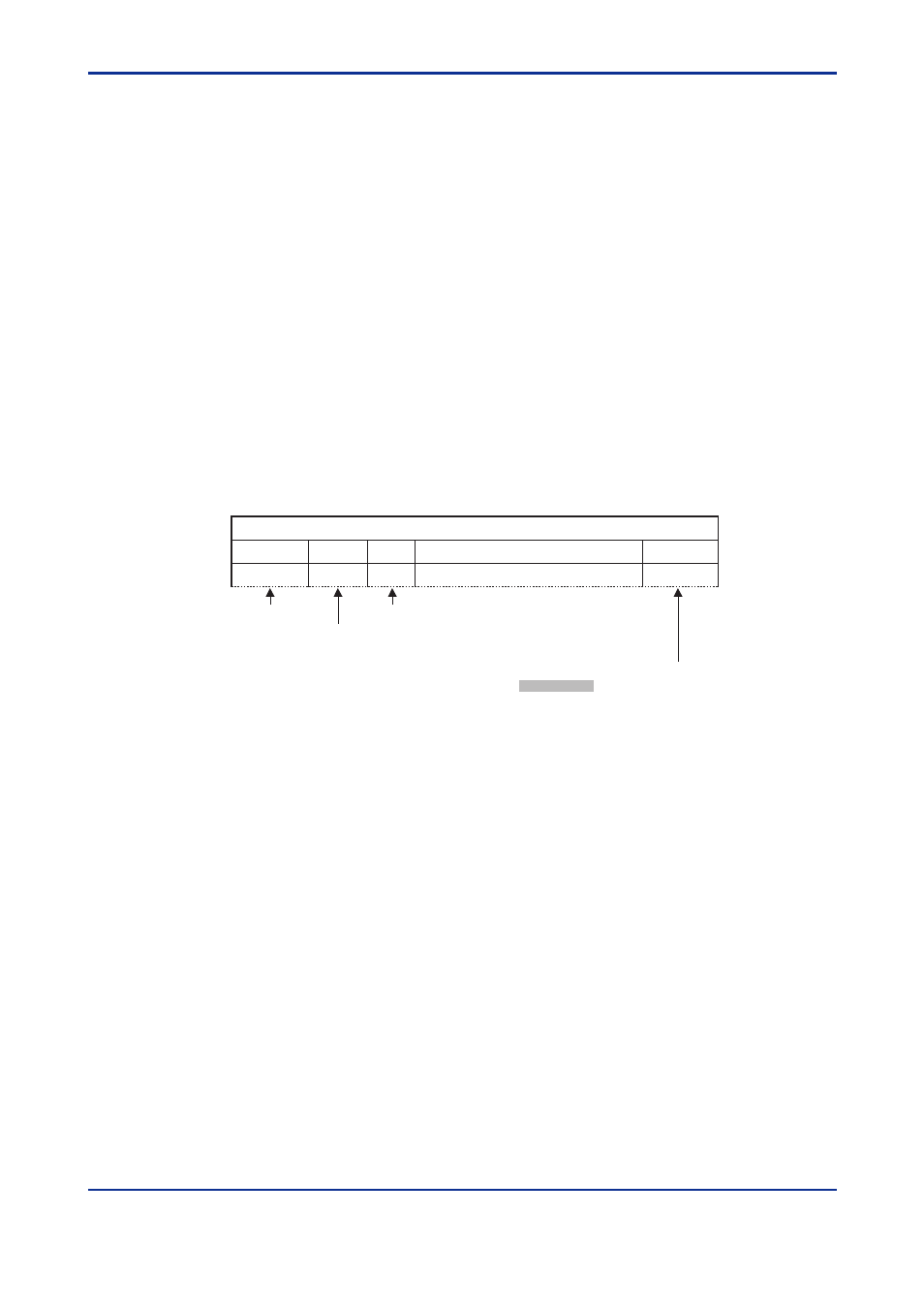
Interpretation of D Register Map Table
This section explains how to read D Register Map tables in this chapter. The num-
bers listed in the leftmost column are D register numbers ((1) below). The five-digit
numbers in the next column are reference numbers used for MODBUS communica-
tion ((2) below). The numbers in the column third from left are register numbers in
hexadecimal used in MODBUS communication programs ((3) below).
D-Reg No.
Ref No.
H No.
Description
R/W
D0001
40001
0000
Status
R
D-Register Data Area
(1) D register number
(2) Reference number (for MODBUS communication)
Permission of read/write by communication
: Indicates that the number of writing
actions is limited to 100,000.
(3) Hex number (for MODBUS communication)