Function, Command/response (for normal operation), Example – Yokogawa JUXTA M Series Digital Limit Alarms MVTK User Manual
Page 32
3-18
<3. PC Link Communication >
IM 77J04J11-01E 1st Edition : 2006.08.25-00
WRM Monitors D registers and I relays on a word-by-word basis
●
Function
Reads the register data that have been specified in advance by the WRS command.
•
Before executing this command, the WRS command must always be executed to
specify which registers are to be monitored. If no register has been specified, error
code 06 is generated.
•
For the format of response in the event of failure, see subsection 3.1.2.
•
The command shown below includes the checksum function.
When performing communication without checksum, do not include the 2-byte
checksum element in the command.
●
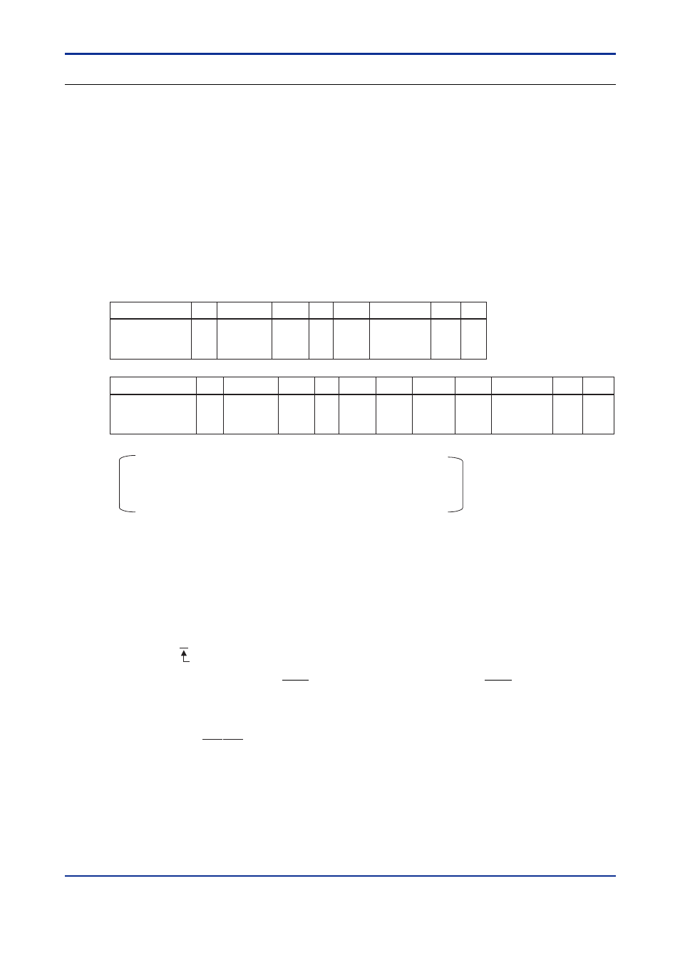
Command/Response (for normal operation)
Number of Bytes
1
2
2
1
3
2
1
1
Number of Bytes
• • •
1
2
2
2
4
4
4
2
1
1
Command
element
STX
Address
number
(ADR)
CPU
number
01
Checksum
0
WRM
ETX
CR
Response
element
STX
OK
dddd1
dddd2
ETX
CR
Address
number
(ADR)
CPU
number
01
• • •
ddddn
Checksum
The response is returned in a 4-digit character string (0000 to FFFF) in hexadecimal.
ddddn: read data of the number of words specified by the WRS command
ddddn is a character string in hexadecimal.
n=1 to 32
●
Example:
Monitoring the alarm-1 setpoint (D0101) and alarm-2 setpoint (D0102) of the M Series with
address number 01.
(This command reads the registers specified by the WRS command.)
[Command]
[STX]01010WRME8[ETX][CR]
CPU number: 01
The alarm-1 setpoint 500 (01F4 [HEX]) and alarm-2 setpoint 500 (01F4 [HEX]) are re-
turned with respect to the above command (50.0 is expressed as 500).
[Response]
[STX]0101OK01F401F412[ETX][CR]