Setup, 1 setup procedure, Connection – Yokogawa JUXTA VJ Series Limit Alarms User Manual
Page 9
<1. Setup >
1-1
IM 77J01J11-01E
1.
Setup
This chapter describes the setup procedure required to use the communication
functions (PC link, Ladder, and MODBUS) and the communication parameters of the
VJ Series.
1.1
Setup Procedure
Set up the communication functions on the VJ Series as follows:
Set up the communication function parameters of the VJ Series. (See section 1.2.)
Connect a higher-level device and a VJ Series. (See the connection diagram below.)
Create communication programs for the higher-level device to perform communication.
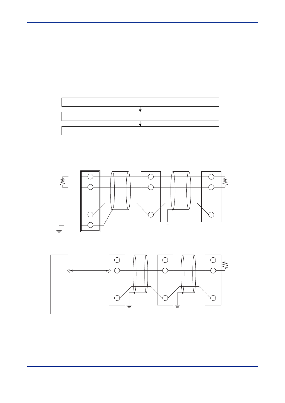
010101E.EPS
Note: Refer to the documentation of each higher-level device when creating communication programs.
B (+)
A (-)
Shielded
B (+)
A (-)
B (+)
A (-)
VJ Series
VJ Series
PLC
Grounding resistance of less than 100
Ω
Grounding resistance of less than 100
Ω
Terminating resistor
220
Ω
1/4 W
Terminating resistor
220
Ω
1/4 W
• Connection
2
5
6
2
5
6
SG
COM
COM
B (+)
A (-)
B (+)
A (-)
B (+)
A (-)
VJ Series
VJ Series
PC or PLC
Grounding resistance
of less than 100
Ω
Terminating resistor
220
Ω
1/4 W
Grounding resistance
of less than 100
Ω
010102E.EPS
2
5
6
2
5
6
COM
COM
ML2
(RS-232C/RS-485 converter)
RS-232C
(straight cable)
4
3
5
SG
3rd Edition : Oct. 15, 2007-00
3rd Edition : Oct. 15, 2007-00