Function, Command/response (for normal operation), Example – Yokogawa JUXTA VJ Series Limit Alarms User Manual
Page 21
<3. PC Link Communication >
3-7
IM 77J01J11-01E
3.2.3
BRR Reading I Relays on a Bit-by-bit Basis in a Random
Order
●
Function
Reads the ON/OFF statuses of I relays by the specified number of bits in a random order.
•
The number of bits to be read at a time is 1 to 32.
•
For the format of response in the event of failure, see subsection 3.1.2.
•
The command shown below includes the checksum function. When performing
communication without a checksum, do not include the 2-byte checksum command
element in the command.
●
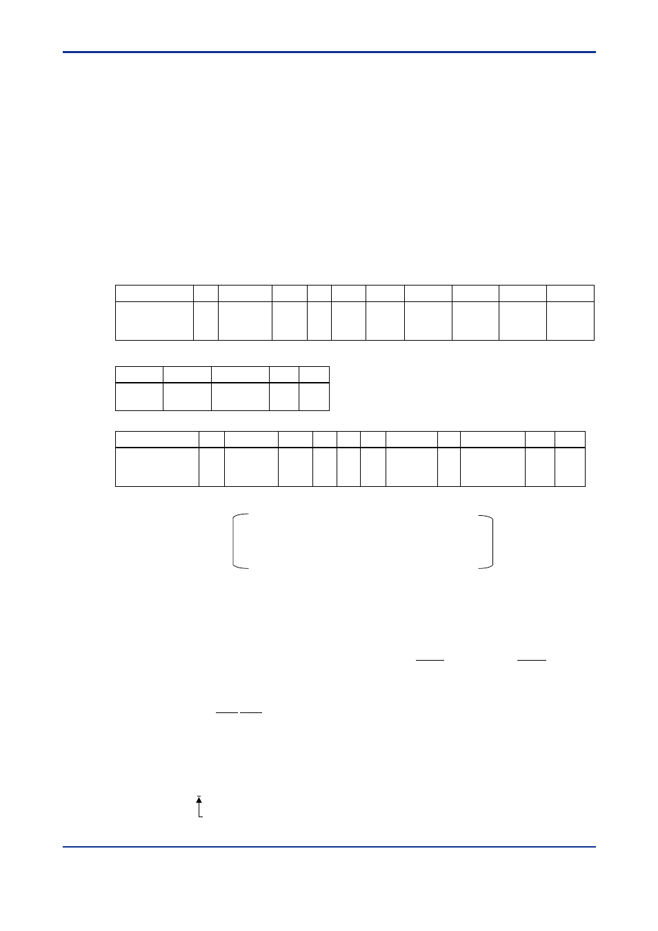
Command/Response (for normal operation)
Number of Bytes
1
2
2
1
3
2
5
1
5
1
Command
Element
STX
Address
number
(ADDRESS)
CPU
number
01
0
BRR
Number
of bits
(n)
I relay
number 1
Comma
or space
I relay
number 2
Comma
or space
• • •
I relay
number n
Checksum
ETX
CR
• • •
5
2
1
1
Number of Bytes
• • •
1
1
2
2
2
1
1
2
1
1
Response
Element
STX
Address
number
(ADDRESS)
CPU
number
01
OK
d1
d2
CR
• • •
dn
Checksum
ETX
The response is “0” when the status is OFF or “1” when ON.
Command (continued)
dn: reads data of the specified number of bits (n=1 to 32)
dn=0(OFF)
dn=1(ON)
030209E.EPS
●
Example:
Reading the statuses of alarms-1 and -2 of the VJ Series signal conditioner with communi-
cation address-1
The following command reads the statuses of alarm-1 (I0009) and alarm-2 (I0010) at
communication address-1.
[Command]
[STX]01010BRR02I0009,I001082[ETX][CR]
With respect to the above command, the ON and OFF responses are returned for alarms-1
and -2 respectively.
[Response]
[STX]0101OK10BD[ETX][CR]
Alarm-1 has been ON.
030210E.EPS
3rd Edition : Oct. 15, 2007-00