1 configuration of message – Yokogawa JUXTA VJ Series Limit Alarms User Manual
Page 42
5-2
<5. MODBUS Communication >
IM 77J01J11-01E
3rd Edition : Oct. 15, 2007-00
5.1.1
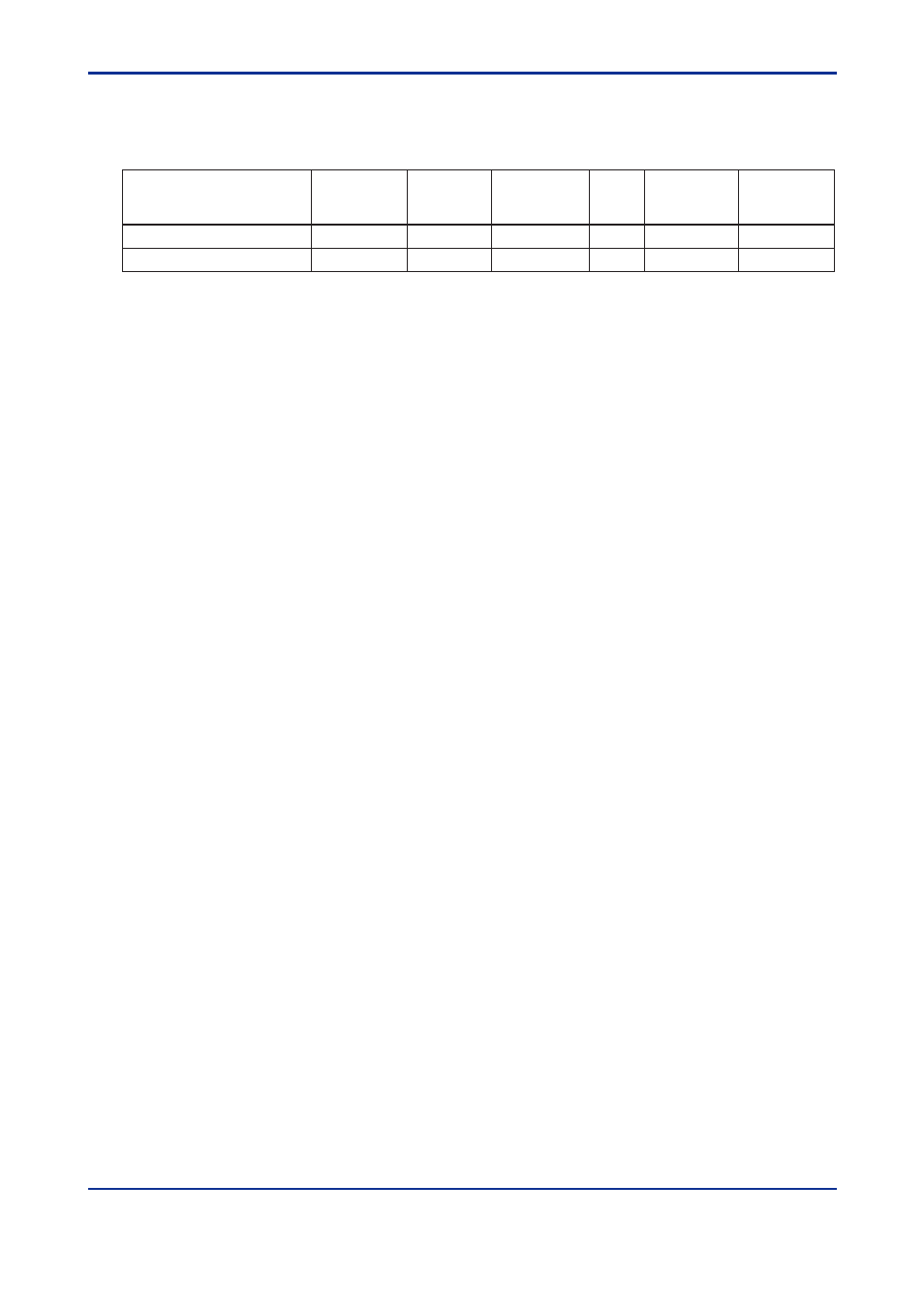
Configuration of Message
Messages sent from the higher-level device to the VJ Series consist of the following ele-
ments.
Number of bytes in RTU mode
None
Number of bytes in ASCII mode
2
2
(1)
(3)
(4)
(5)
(2)
(6)
Element
Address
Number
(ADDRESS)
Function Code
Start of
Message Mark
Data
Error Check
End of
Message Mark
None
1
2
2
4n
1
1
2n
2
050103E.EPS
(1)
Start of Message Mark
This mark indicates the start of a message. Note that only ASCII mode requires a
colon (:).
(2)
Address Number (1 to 99)
Address numbers are used by the higher-level device to identify the VJ Series signal
conditioners at the communication destination. (These numbers are identification
numbers specific to individual VJ Series, which are expressed in a hexadecimal in the
message.)
(3)
Function Code (See subsection 5.2.1, “List of Function Codes”)
This element specifies a command (function code) from the higher-level device.
(4)
Data
This element specifies D register numbers, the number of D registers, parameter
values, or others in accordance with the function code. (It is expressed in a hexadeci-
mal in the message.)
(5)
Error Check
In RTU mode
Carried out by the cyclic redundancy check (CRC-16) system.
In ASCII mode
Carried out by the longitudinal redundancy check (LRC) system.
(6)
End of Message Mark
This mark indicates the end of a message. Note that only ASCII mode requires CR +
LF.