Functions and usage of d registers, 1 overview of d registers, 2 interpretation of d register map table – Yokogawa JUXTA VJ Series Limit Alarms User Manual
Page 51
<6. Functions and Usage of D Registers >
6-1
IM 77J01J11-01E
3rd Edition : Oct. 15, 2007-00
6.
Functions and Usage of D Registers
6.1
Overview of D Registers
This section describes the functions and usage of D registers.
The D registers store the input and output values, statuses, and others that are
handled by the VJ Series signal conditioners. By connecting VJ Series signal condi-
tioners to higher-level equipment capable of PC link communication, Ladder com-
munication, or MODBUS communication, you can readily use these internal data
items by reading from or writing to the D registers.
6.2
Interpretation of D Register Map Table
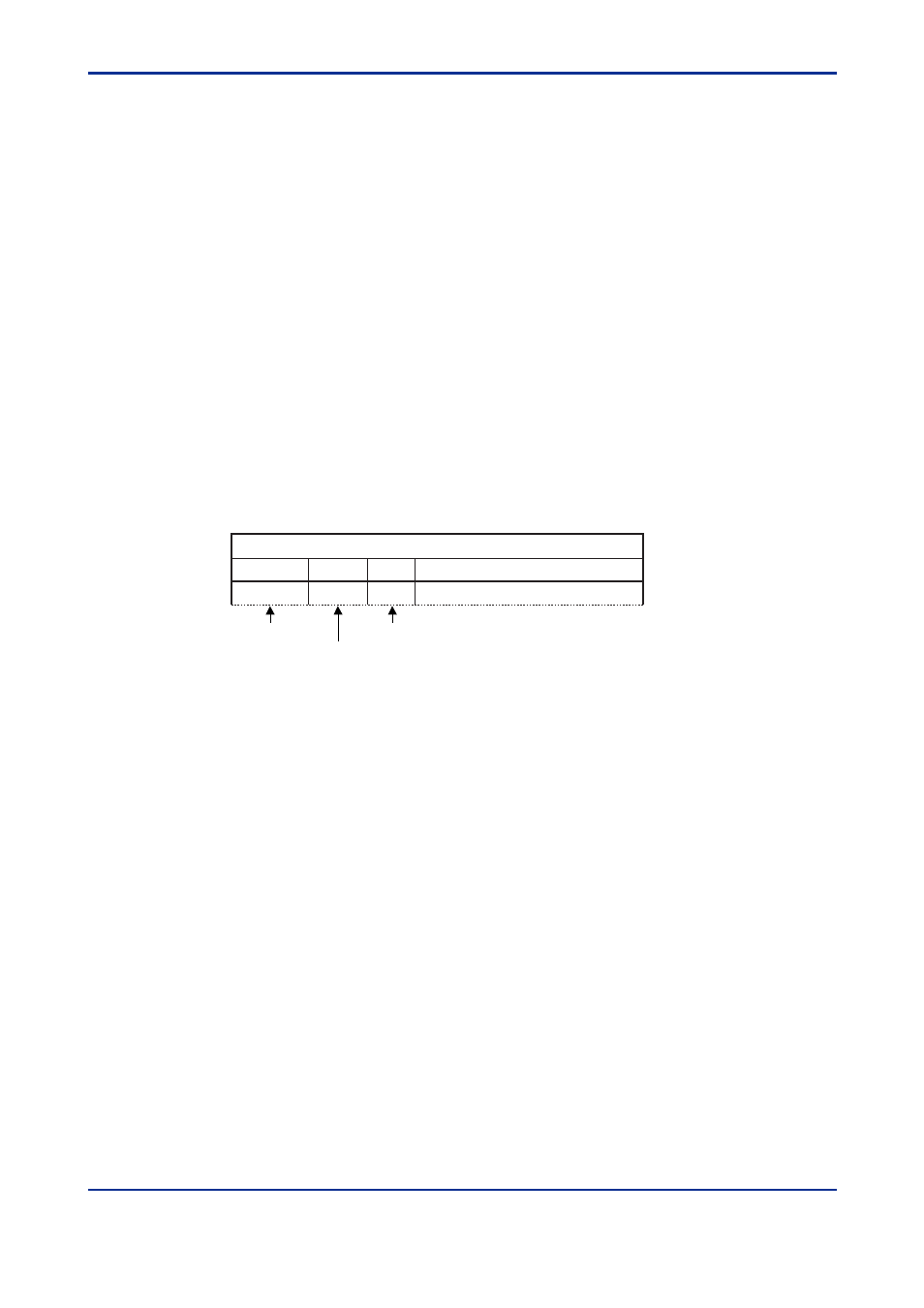
This section explains how to interpret the "D Register Map" table. In the example
shown below, the number in the leftmost column denotes the register number "1."
The five-digit number in the column on the immediate right of the leftmost column
represents the reference number for MODBUS communication "2." The number in
the column third from left is the register number (hexadecimal) for the MODBUS
communication program "3."
D-Reg No.
Ref No.
H No.
Description
D0001
40001
0000
Status
Name of D Register Map
060201E.EPS
(1) D register number
(2) Reference number (for MODBUS communication)
(3) Hex number (for MODBUS communication)