Modbus communication, 1 overview – Yokogawa JUXTA VJ Series Limit Alarms User Manual
Page 41
<5. MODBUS Communication >
5-1
IM 77J01J11-01E
3rd Edition : Oct. 15, 2007-00
5.
MODBUS Communication
5.1
Overview
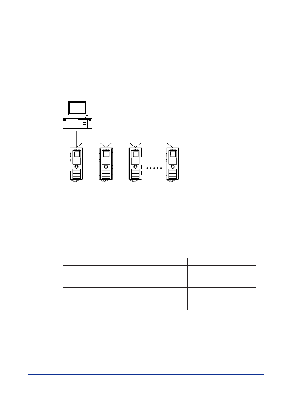
The use of MODBUS communication allows the VJ Series signal conditioners to
communicate with a PC. In this communication, a PC reads data from D registers,
internal registers of the VJ Series.
Hereafter, PCs are generally called "higher-level devices."
Maximum overall cable length of 1200 m
for a maximum of 31 substations
PC
050101E.EPS
Figure 5-1 Example of Connection for MODBUS Communication
See Also
Chapter 6 for information on the D registers.
For MODBUS communication with the VJ Series, we provide the ASCII mode and RTU
mode (binary system) for the transmission mode.
Table 5-1 ASCII and RTU Modes
Item
ASCII Mode
RTU Mode
Number of data bits
7 bits (ASCII)
8 bits (binary)
: (colon)
Not necessary
Message end mark
Message start mark
CR+LF
Not necessary
Message length (*1)
Error detection
2N+1
N
Data time intervals
1 second or less
24 bit time or less (*2)
Longitudinal redundancy check: LRC Cyclic redundancy check: CRC-16
050102E.EPS
*1:
When message length in the RTU mode is assumed to be "N"
*2:
For a communication rate of 9600 bps, 1
Ϭ
9600
ϫ
24 seconds or less applies.
In MODBUS communication, a higher-level device identifies each VJ Series signal condi-
tioner with a communication address of 1 to 99.