2 commands/responses at the plc, 1 command/response component elements – Yokogawa JUXTA VJ Series Limit Alarms User Manual
Page 38
4-2
<4. Ladder Communication >
IM 77J01J11-01E
4.2
Commands/Responses at the PLC
The PLC sends commands and receives responses to commands. The commands
and responses that can be used are as follows.
4.2.1
Command/Response Component Elements
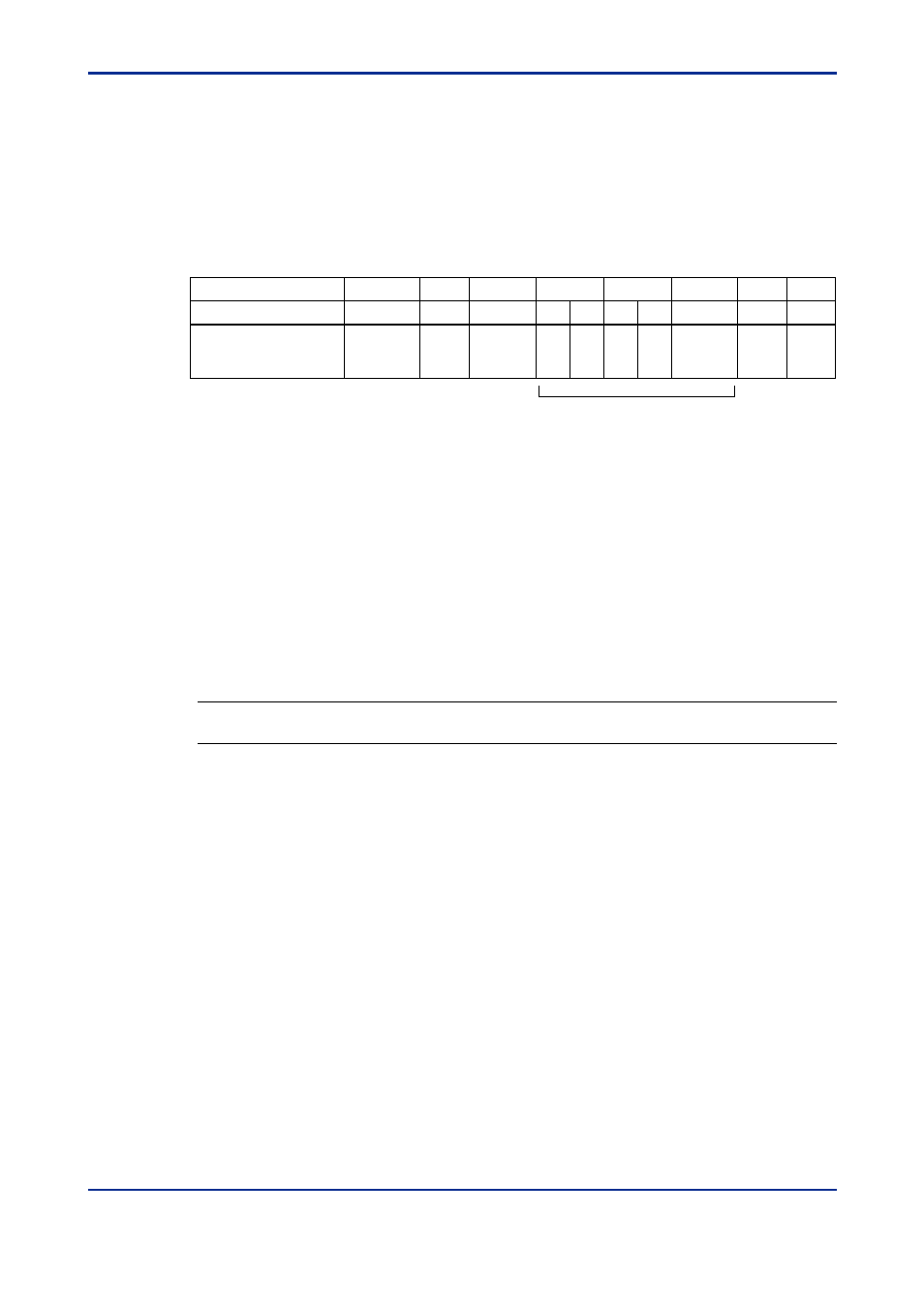
Commands sent from the PLC to the VJ Series signal conditioners are configured as
shown below.
Number of Bytes
1
1
2
2
1
1
1
1
Number of BCD Digits
2
2
1
4
4
2
2
1
1
1
Command/Response
Element
Address
number
(ADDRESS)
Parameter
number
CPU
number
01
CR
(0D)
LF
(0A)
5th
digit
0
+/-
0
Data
040201E.EPS
Variable only for responses.
A maximum of 64 data items
(1)
Address number (01 to 99)
Numbers used by the PLC to identify the VJ Series signal conditioners at the commu-
nication destination. (They are identification number specific to individual VJ Series
signal conditioners.)
(2)
CPU number
This number is fixed to “01”.
(3)
Parameter number
This is 4-digit BCD data of a D register number, not including "D." No I-relays can be
specified.
See Also
Chapter 6 for more information on D registers.
(4)
0
This is fixed to "0."
(5)
0
This is fixed to "0" for commands, while it is 5th digit of read data for responses.
(6)
0
This is fixed to "0."
(7)
+/-
This is fixed to "0" for commands, while it is 0: positive data (+) or 1: negative data (-)
for responses.
(8)
Data
This is data to be read for commands, while it is the number of read data for re-
sponses.
(9)
CR and LF
These are the control codes indicating the end of a command. The corresponding
control character strings are CR, which is 0D in hexadecimal in ASCII code, and LF,
which is 0A in hexadecimal in ASCII code.
3rd Edition : Oct. 15, 2007-00