Hart communicator operation, 1 conditions of communication line, 2 communication line requirements – Yokogawa Wireless Temperature Transmitter YTA510 User Manual
Page 9: Hart communicator operation -1, Conditions of communication line -1, Communication line requirements -1, 1 conditions of communica- tion line
2. HART COMMUNICATOR OPERATION
IM 01C50T01-01E
2-1
2.
HART COMMUNICATOR OPERATION
2.1 Conditions of Communica-
tion Line
2.1.1 Interconnection Between YTA
and HART Communicator
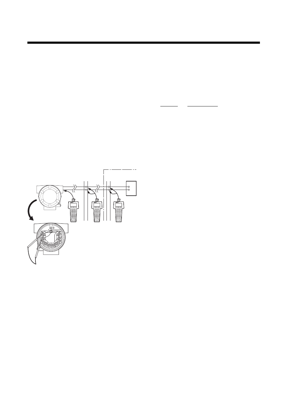
The HART communicator can interface with the
transmitter from the control room, the transmitter site,
or any other wiring termination point in the loop,
provided there is a minimum of 250W between the
connection and the power supply. To communicate, it
must be connected in parallel with the transmitter; the
connections are non-polarized. Figure 2.1 illustrates the
wiring connections for direct interface at the transmit-
ter site for the YTA. The HART communicator can be
used for remote access from any terminal strip as well.
HART communicator
HART
communicator
YTA
Distributor
Control room
Terminal board
Relaying
terminals
F0201.EPS
Figure 2.1 Interconnection Diagram
2.1.2 Communication Line
Requirements
Specifications for Communication Line:
Supply voltage
General use type; 16.4 to 42 V DC
Load resistance; 250 to 600
Ω
(Including cable resistance)
Minimum cable size; 24 AWG,
(0.51 mm diameter)
Cable type; Single pair shielded or
multiple pair with overall shield
Maximum twisted-pair length; 10,000 ft
(3,048 m)
Maximum multiple twisted-pair length;
5,000 ft (1,524 m)
Use the following formula to determine cable length
for a specific application;
L =
–
65
×
10
6
(R
×
C)
(C
f
+10,000)
C
where: L = length in feet or meters.
R = resistance in ohms, current sense
resistance plus barrier resistance.
C = cable capacitance in pF/ft or pF/m.
C
f
= Maximum shunt capacitance of field
devices in pF.