6 tag no, 5 detailed setup, 1 device information – Yokogawa Wireless Temperature Transmitter YTA510 User Manual
Page 24: 2 test output, 3 burnout function, Tag no -11, Detailed setup -11, Device information -11, Test output -11, Burnout function -11
3. OPERATION
IM 01C50T01-01E
3-11
3.4.6 Tag No.
To change the Tag, see section 2.2.4 “Entering, setting
and Sending Data”.
Up to 8 characters can be set with “Tag”.
Example: To change from Tag “
YOKOGAWA
” to “
FIC-1A
.”
YTA :YOKOGAWA
Tag No.
YOKOGAWA
YOKOGAWA
HELP
DEL
ESC
ENTER
1. Device setup
3. Basic Setup
1. Tag
Enter new setting and press
ENTER[F4]
.
Call up the “
Tag
” setting display.
See Section 2.2.4.
3.5 Detailed Setup
3.5.1 Device Information
Following Device information can be entered.
Tag :
Up to 8 characters.
Tag Extension:
Extension of Tag description. Up
to 8 characters.
Descriptor:
Up to 16 characters
Message:
Up to 32 characters
Date:
mm/dd/yy mm:month, dd:day,
yy:year
Call up the “Device Information” display. [1.Device
setup
→
4.Detailed setup
→
4.Device information]
3.5.2 Test Output
This feature can be used to output a fixed current from
3.6 mA (-2.5%) to 21.6 mA (110%) for loop checks.
Call up the “Loop test ” display. [1.Device setup.
→
2.Diag/Service
→
2.Loop test]
Put the control loop in manual mode by pressing
OK[F4]
. The following output selections are offered.
4mA:
Outputs 4 mA current
20 mA:
Outputs 20 mA current
Other:
Sets a desired output in mA using
alphanumeric keys.
End:
Exits
CAUTION
1. Test output is held for approximately 10
minutes, and then released automatically
after the time has elapsed. If the HART
communicator power supply is turned off or
communication connector is disconnected
during the test output operation, it is held for
approximately 10 minutes.
2. Press the
key to release the test output
immediately.
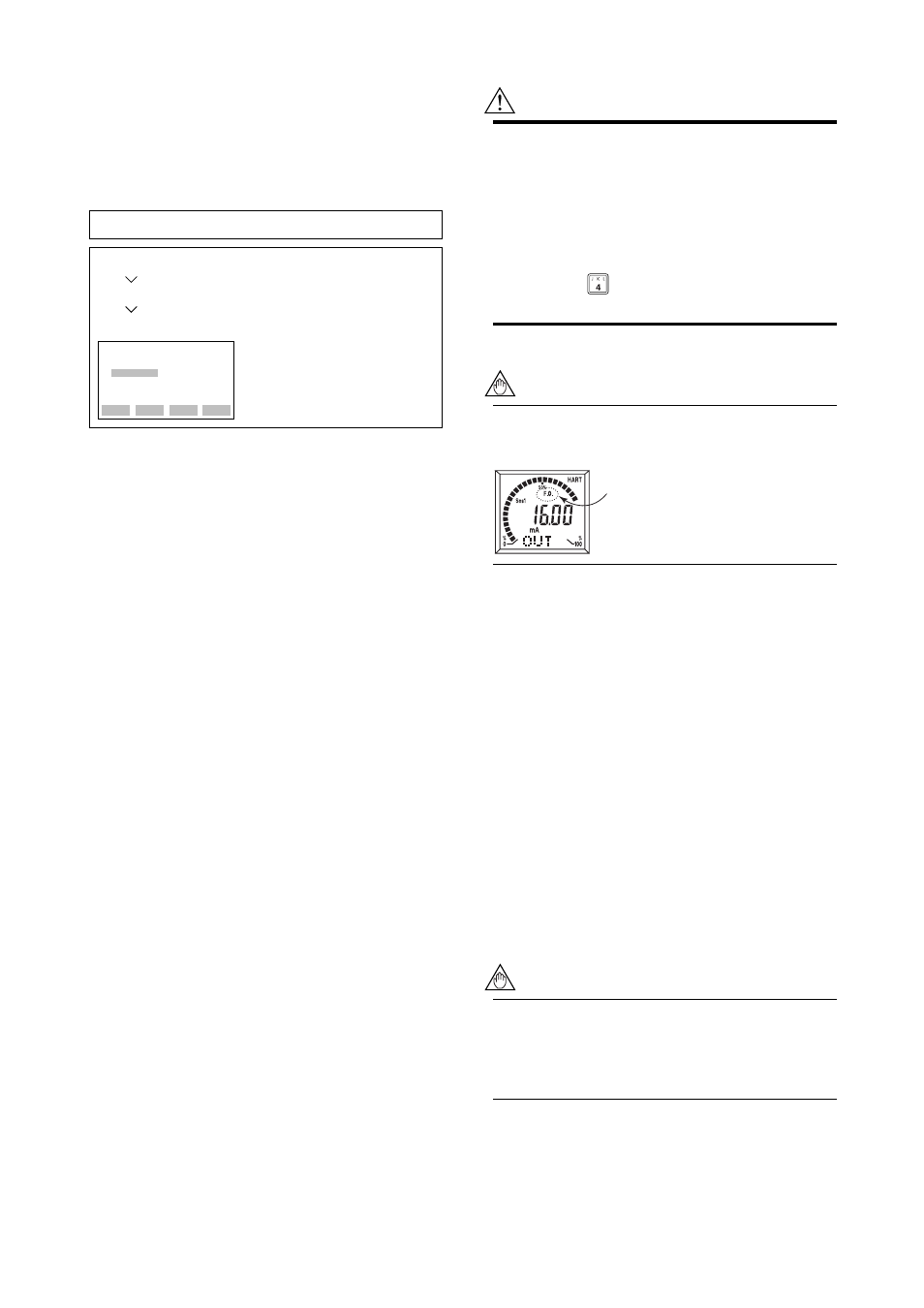
NOTE
If the transmitter is equipped with the integral
indicator, the LCD displays F.O.
F0304.EPS
"F.O." lit on.
3.5.3 Burnout Function
a) Sensor burnout
Configure the burnout mode in the case of sensor
failure or disconnection.
Call up the “Snsr burnout type” display. [1.Device
setup
→
4.Detailed setup
→
3.Output condition
→
1.Analog output
→
5.Snsr burnout ]
When the sensor failure is detected, the transmitter
outputs one of the following values.
Low:
Outputs 3.6mA
High:
Outputs 21.6mA
User(mA):
Outputs user set value in mA. Settable
within 3.6 to 21.6 mA.
User(%):
Outputs user set value in %. Settable
within -2.5 to 110 %.
Off:
The burn out output is NOT defined
NOTE
When sensor burnout is set to “off”, the
transmitter's output will go undefined at sensor
failure. It is necessary to understand this point
well when setting “off”.