4 integral indicator display mode, Integral indicator display mode -12 – Yokogawa Wireless Temperature Transmitter YTA510 User Manual
Page 25
3. OPERATION
IM 01C50T01-01E
3-12
During sensor burn out time, the Sensor1 failure or the
Sensor2 failure error message is generated. (See
Section 3.6.1 for details.)
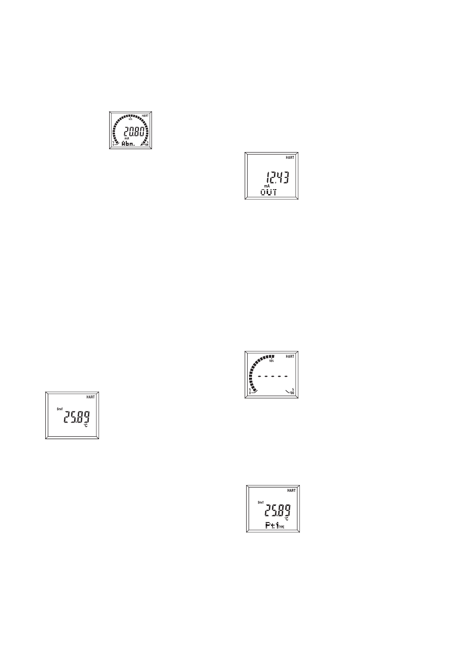
If the transmitter is equipped with the integral indica-
tor, the LCD displays “Abn.” as shown in Figure 3.2.
F0306.EPS
Displays "Abn."
Figure 3.2 Integral Indicator Display in Sensor
Burn Out
b) Burnout in hardware failure
The output status of the transmitter in hardware
failure is set using a jumper on the CPU assembly.
The current setting can be checked in parameter
“AO Alrm type”.
Call up the “AO Alrm type parameter” display.
[1.Device setup
→
4.Detailed setup
→
3.Output
condition
→
1.Analog output
→
2.AO Alrm typ].
3.5.4 Integral Indicator Display Mode
When an integral indicator is specified with the
transmitter, the display items and update speed can be
configured.
Call up the”Meter output” display [1.Device setup
→
4.Detailed setup
→
3.Output condition
→
3.Meter
output ]
1) Display selection
(a) Process Disp
To Specify process variables to
be shown on the digital display.
Process variables and output
value(see (b)) are shown on the
digital display in turn. Select-
able from followings;
PV
SV
TV
4V
PV, SV
PV, SV, TV
PV, SV, TV, 4V
Inhibit
If two or more variables are
specified, each value appears
one after another in order. The
unit corresponding to each
process variable is lit. If
“Inhibit” is selected, no process
variable is displayed.
(b) % /mA Disp
To Specify output value to be
shown on the digital display.
Select from following;
mA
%
mA, %
Inhibit
If two values are selected, they
will appear on the display one
after another. Process variables
and output value(see (a)) is
shown on the digital display in
turn. The unit corresponding to
each output value is lit. If
“Inhibit” is selected, no ourput
value will be displayed.
(c) Err-No Disp
To Select whether error codes
are shown on the digital display
or not when an error occurs.
When “Show” is selected, error
code will be shown on the
digital display. When “Inhibit”
is selected, no error code will
be shown on the digital display.
(d) Bar graph
To select whether the output
bar-graph display is lit or not.
When “Show” is selected, The
output value is shown in a 32-
segment bar-graph. If “Inhibit”
is selected, the bar-graph is off.
(e) Matrix Disp
To select information to be
shown on the dot matrix
display.
Process:Display name of the
process variable shown on
the digital display. (Ex.
PV)
Type:
Display type of the input
sensor
Wire:
Display the number of
wires of the input sensor.
F03541
Displays PV value.
F03542
Displays output value.
F03543
Displays PV value and
sensor type
F03542
Displays bar graph.