Yokogawa Wireless Temperature Transmitter YTA510 User Manual
Page 37
IM 01C50T01-01E
4-2
4. PARAMETERS LISTS
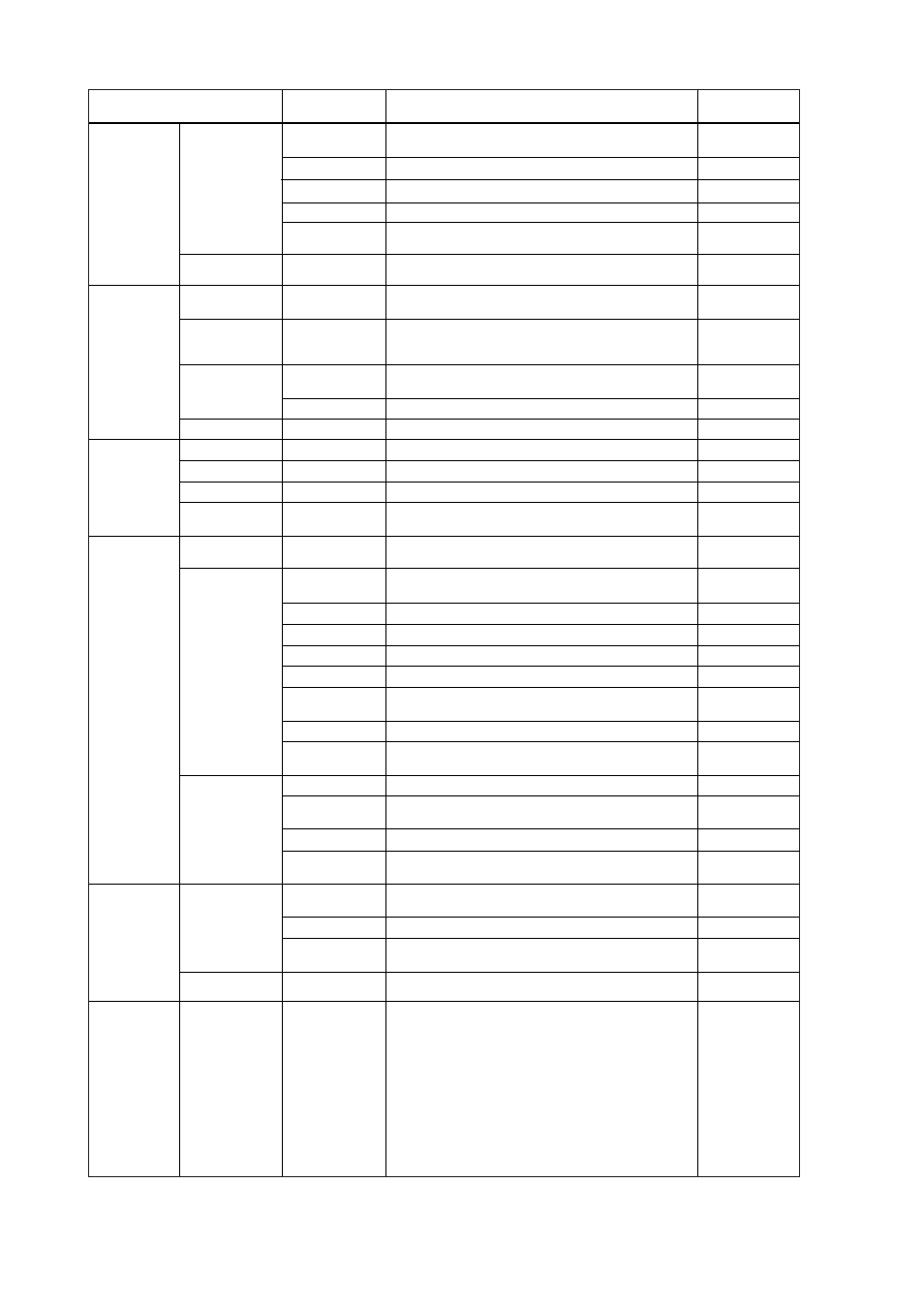
(1)PV (2)SV (3)TV (4)4V (5)PV,SV (6)PV,SV,TV
(7)PV,SV,TV,4V (8)Inhibit
(1)mA (2)% (3)mA,% (4)Inhibit
Show or Inhibit
Show or Inhibit
(1)Process (2)Type (3)Wire (4)Process,Type
(5)Type,Wire (6)Inhibit
Fast, normal, or slow.
Low, High, off, or user-setting value (mA or %).
Show the current setting of the output direction in
hardware failure which is set using jumper on a CPU
assembly.
(1)PV, (2)output in % range & current, (3)PV and output
in current.
Enable/disable the burst mode.
0 to 15.
Process variables.
% Output variable
4 to 20 mA Output variable
Terminal temperature variable
Output can be set from 4, 20 mA or the designated
value within 3.6 to 21.6 mA.
Check the transmitters’s status. If an error is detected,
the corresponsing message is displayed.
Reset the CPU and check the transmitters’s status.
Display of the result of self-test transmitter.
Show/not show warning messages. OFF or ON.
Up to 4 error histories are stored in EEPROM.
Maximum and Minimum value of PV, SV, TV, 4V and
Terminal Temperature during the operation.
Operation time from last power-on.
Un-intentional loss of during the operation may be
detected. START or STOP.
Displays the permit/protect status for setting changes.
Write protect status is released for 10 minutes when the
password is entered.
Setting a new password. 8 alpha numeric characters.
Show the status if the joker password was used.
Keep(not used), Break(used)
(1)V.R. / ZERO&GAIN (2)V.R. / ZERO (3)Temp /
ZERO&GAIN (4)Temp / ZERO
(1)On (2)Off (3)Clear
Give correction to the interpretation of a temperature
input to the characterization curve stored in a transmitter.
Adjust the output points of 4 mA and 20 mA.
Yokogawa
YTA110/YTA310/YTA320
Lower Limit for PV setting.
Upper Limit for PV setting.
Lower Limit for Sensor 1(2)
Upper Limit for Sensor 1(2)
Sensor1(2) serial number information
Process Disp
%/mA Disp
Error-No Disp
Bar graph
Matrix Disp
Disp update
Snsr burnout type
AO Alrm typ
Burst option
Burst mode
Poll addr
PV,SV,TV,4V
PV % rnge
PV AO
Term
Loop test
Self test
Master test
Status
Set warning enbl
Error log view
Max/Min log
Operate Time
Power Check
Write protect
Enable wrt
10 min
New password
Software seal
Input trimming
mode
Snsr1(2) trim act
S1(2)
trim zero/gain
D/A trim, Scaled
D/A trim
Destributor
Model
Dev.id
Final asmbly num
Universal rev
Fld dev rev
Software rev
PV LSL
PV USL
Snsr1(2) LSL
Snsr1(2) USL
Snsr1(2) Snsr s/n
Display
(see note 3)
Output
Monitoring
Maintenance
Adjustment
Referential
Information
Display select
Display update
period
Sensor burn-out
Output
Output in CPU
failure
Burst mode
Multi-drop mode
Process Variable
Output in %
Output in mA
Terminal
Temperature
Test Output
Self-diagnostics
Write Protect
Sensor trim
(Sensor1/2)
Analog output
trim
T0401_2.EPS
Item
Selection / Setting Range
Initial Setting
HART
Communicator
PV
mA
Show
Show
Process
Normal
High*
High*
—
disable
0
—
—
—
—
—
—
—
—
All OFF
—
—
—
STOP
NO
—
—
—
—
—
—
Note 3:
Appears only when Integral Indicator is specified.