7 analog output trim, Analog output trim -15 – Yokogawa Wireless Temperature Transmitter YTA510 User Manual
Page 28
3. OPERATION
IM 01C50T01-01E
3-15
2. Call up the “Snsr1 inp trim” display. [1.Device
setup
→
2. Diag/Service
→
3.Calibration
→
3.Sensor Trim
→
1.Snsr 1 inp trim]
3. Select “2.Input Trimming Mode”. The following
selections are offered.
V.R. / ZERO&GAIN
V.R. / ZERO
Temp / ZERO&GAIN
Temp / ZERO
Select “V.R. / ZERO&GAIN” or “V.R. / ZERO”
when the calibration device is DC voltage generator
or Variable resistor or select “TEMP /
ZERO&GAIN” or “TEMP / ZERO” when the
device is Temperature sensor.
4. Enable the user trim. Select “3. Snsr1 Trim Act”.
The following selections are offered.
On:
Use User trim value
Off:
Ignore User trim value, and return to the
factory setting.
Clear: Clear User trim value and return to the
factory setting.
Select “On” to enable trim function and Press
ENTER[F4]
.
5. Perform zero-adjustment. Call up the “4. S1 Trim
Zero/Gain”.
(a) When the input trimming mode is “V.R. /
ZERO&GAIN” or “V.R. / ZERO”, apply the value
for the zero-point shown in the table 3.2 depending
on the specified sensor type. Wait until the input
from the calibration device becomes stable.
(b) When the input trimming mode is “TEMP /
ZERO&GAIN” or “TEMP / ZERO”, expose the
temperature sensor to calibration temperature for
the zero-point. Wait until the input from the
temperature sensor becomes stable.
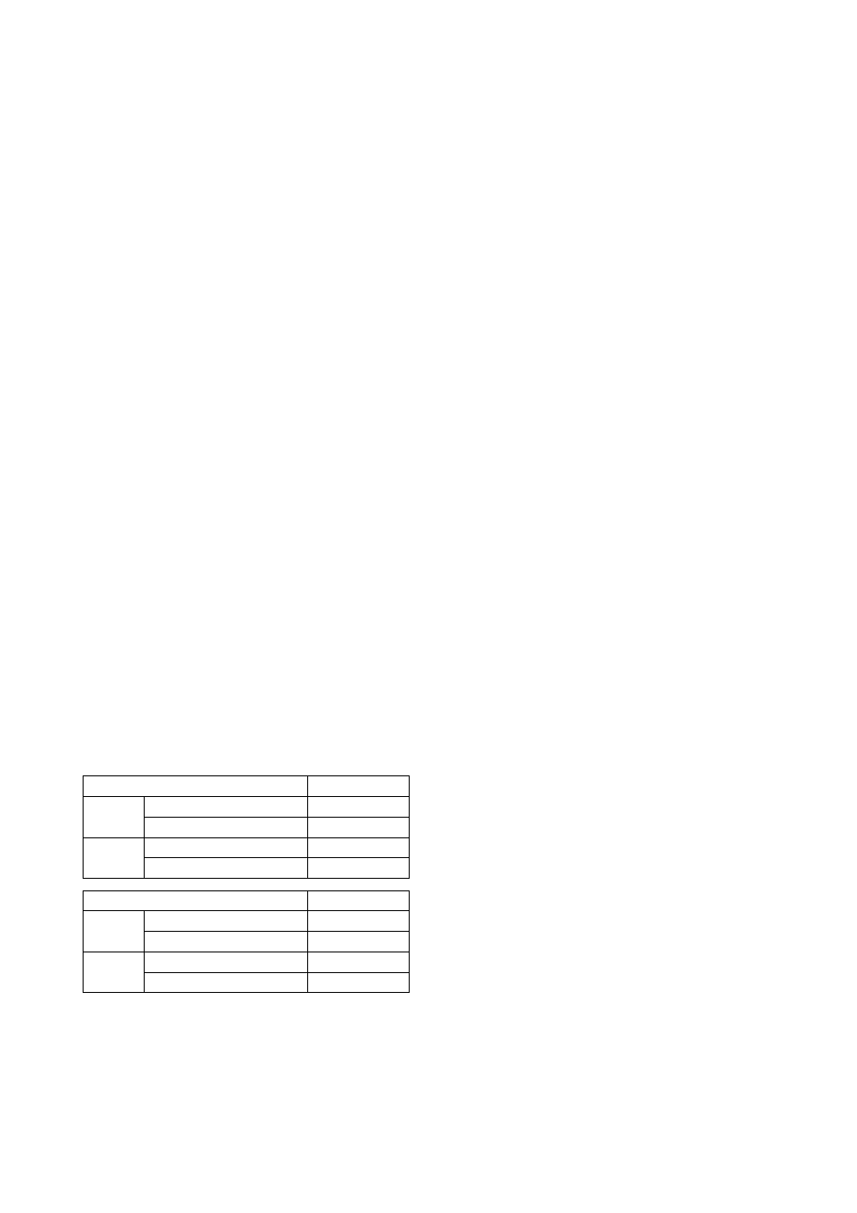
Table 3.2
Sensor type
Zero-point value
TC, mV
RTD, ohm
B,R,S,T
E,J,K,N,W3,W5,L,U,mV
Pt100, JPt100, Ni120, Cu
Pt200, Pt500, ohm
0 mV
0 mV
40
Ω
40
Ω
Sensor type
Gain-point value
TC, mV
RTD, ohm
B,R,S,T
E,J,K,N,W3,W5,L,U,mV
Pt100, JPt100, Ni120, Cu
Pt200, Pt500, ohm
25 mV
75 mV
330
Ω
1600
Ω
T0302.EPS
6. Press
OK[F4]
.
7. Enter Zero trim reference value from key pad, and
press
ENTER[F4]
.
Perform the following steps when the input trim-
ming mode is “V.R. / ZERO&GAIN” or “Temp /
ZERO&GAIN”.
8. Perform gain-point adjustment.
(a) When the input trimming mode is “V.R. /
ZERO&GAIN”, apply the value for the gain-point
shown in the table 3.2 depending on the specified
sensor type. Wait until the input from the calibra-
tion device becomes stable.
(b) When the input trimming mode is “Temp /
ZERO&GAIN”, expose the temperature sensor to
calibration temperature for the gain-point. Wait
until the input from the temperature sensor becomes
stable.
9. Press
OK[F4]
.
10. Enter Gain trim reference value from key pad, and
press
ENTER[F4]
.
Follow outlined procedures to perform Sensor2 trim.
3.5.7 Analog Output Trim
Fine output adjustment is performed with “D/A trim”
or “Scaled D/A trim”.
●
D/A Trim
D/A trim is to be performed if the digital ammeter used
for calibration does not read 4.000mA and 20.000mA
exactly when the output signal is 0% and 100%.
Procedures
1. Call up the “D/A trim” display. [1.Device setup
→
2. Diag/Service
→
3.Calibration
→
4.AO D/A Trim
→
1.D/A trim]
2. Press
OK[F4]
to set the transmitter to manual
mode.
3. Connect the ammeter(
±
1
µ
A is measurable) and
press
OK[F4]
.
4. Press
OK[F4]
to make the transmitter output 4
mA(0%) . Check the reading of the ammeter, and
enter this value using the key pad and Press
ENTER[F4]
.
5. Next, press
OK[F4]
to make the transmitter output
20 mA (100%) . Check the reading on the ammeter,
and enter this value using the key pad.
6. After completing the above steps, return the
transmitter to automatic control.
●
Scaled D/A trim
Scaled D/A trim can be performed to adjust the output
when using a voltmeter or the other meters scaled to 0
to 100 %.