5 damping time constant, Damping time constant -10 – Yokogawa Wireless Temperature Transmitter YTA510 User Manual
Page 23
3. OPERATION
IM 01C50T01-01E
3-10
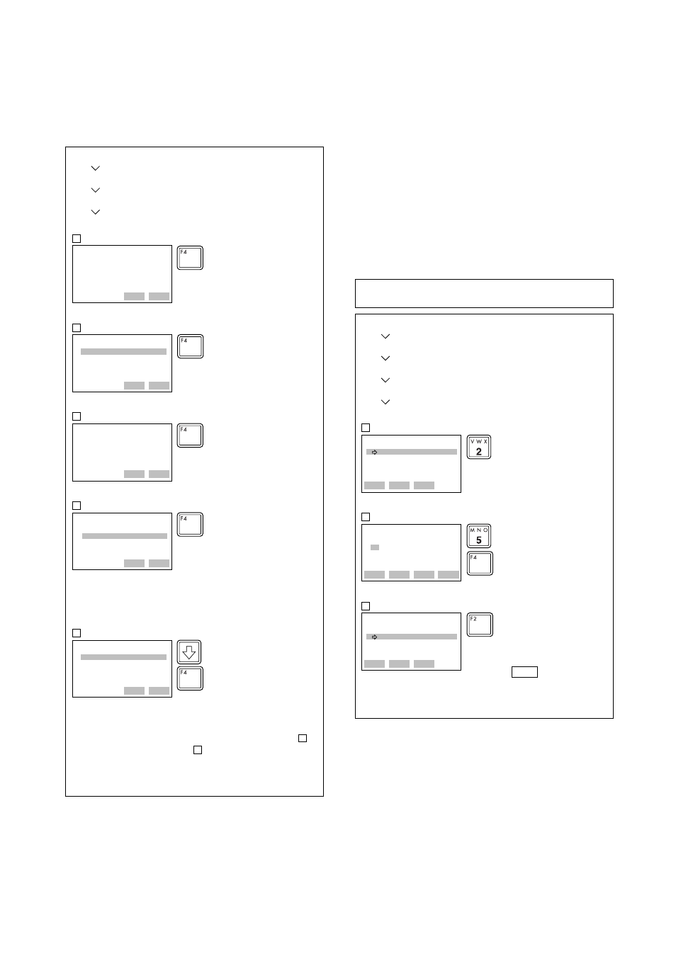
(2) Changing the range while applying an
actual input – Apply values –
This feature allows the lower and upper range
values to be setup automatically with the actual
input applied.
YTA:
WARN-Loop should be
removed from
automatic control
HELP
SAVE
ABORT
OK
1
YTA :
Set the:
1 4mA
2 20mA
3 Exit
HELP
SEND
ABORT
ENTER
2
1. Device setup
2. Diag/Service
3. Calibration
1. Apply values
YTA :
Apply new 4ma input
HELP
SEND
ABORT
OK
3
YTA :
Current applied
process value:50.10 degC
1 Set as 4mA value
2 Read new value
3 Leave as found
HELP
SEND
ABORT
ENTER
4
YTA :
Set the:
1 4mA
2 20mA
3 Exit
HELP
SEND
ABORT
ENTER
5
4
3
Press
OK[F4]
to make the control
loop manual.
Call up “
Apply Values
” display.
To set the lower range value, select
“
1. 4mA
” and press
ENTER[F4]
.
Apply the input which corresponds
to 4mA. After obtaining stable input,
press
OK[F4]
.
Select “
2. 20mA
” and press
ENTER[F4]
. Apply the value which
corresponding to 20mA and enter it
as URV. (Refer to procedures
and .)
After completing the range change,
select “
3.Exit
” and press
ENTER[F4]
.
The LRV to be changed is 50.10
degC.
• Selecting item 1 sets LRV to
50.10degC.
• Selecting item 2 reads LRV
again.
To set LRV to “
50.10
”, select item 1
and press
ENTER[F4]
.
3.4.5 Damping Time Constant
Setting the response time of each Process Variable to
make it vary slowly with a rapid change in input. Set
the value from 0 to 99 seconds.
If the time constant is set to 2 seconds, Transmitter
calculates a reading every cycle time using the damp-
ing equation, to make the output 63 percent of the
input range after 2 seconds.
This damping time constant is normally set to work
when the temperature makes a step change within 2
percent of the output range. The damping can be
changed using the “PV damp point” parameter .
YTA :
PV Unit&Damp
1 PV Unit degC
2 PV Damp 2 s
3 PV damp point 2 %
HELP
SAVE
HOME
ENTER
1
YTA :
Snsr1 damp
2 s
5
HELP
SAVE
ABORT
ENTER
2
1. Device setup
1. Process variables
2. Variable setting
Unit & Damp
1. PV Unit&Damp
YTA :
PV Unit&Damp
1 PV Unit degC
2 PV Damp 5 s
3 PV damp point 2 %
HELP
SEND
HOME
ENTER
3
SEND
Example: To set the damping time constant for PV to “
5
”
seconds.
Enter “
2
” to call up “
PV damp
”
display.
Enter new value, and press
ENTER[F4]
.
Press
SEND[F2]
to send the
setting to the transmitter.
Check that disappears.
# When necessary, change the
setting of “PV damp point”.
Call up “
PV Unit&Damp
” display.