2 ramc options, 2 options -2, 2 options – Yokogawa RAMC User Manual
Page 74
<9. TECHNICAL DATA>
9-2
IM 01R01B02-00E-E 10th edition January 01, 2013 -00
All Rights Reserved. Copyright © 2003, Rota Yokogawa
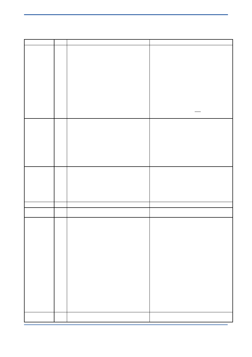
9.2 Options
Options
Code
Description
Restriction
Indicator
/A5
/A12
/A13
/A14
/A16
/A17
/A18
/A20
/A21
/A22
/A23
/A25
/A26
Thread for cable gland ASME ½´´ NPT female
US- engineering units
Thread for cable gland ISO M20 x 1,5 female
Housing color green
Indicator on 95 mm extension
Housing color green
Housing color yellow
Scale for type T66
Scale and EEPROM for type E66, H66, G66
Scale for type T90, T91
Scale and EEPROM for type E90, H90, G90, E91, H91,
G91
Pressure balance element
Indicator for -40°C ambient temperature
Not with /A13
Only for indicator E, H
Not with /A5, /KF1,/NF1, /KS2
Only for housing 91
Only for housing 90 + 91
Only for housing 90
Only for housing 90
Not with hazardous approval type; not with indicator
Not with hazardous approval type not with indicator
Not with hazardous approval type; not with indicator
Not with hazardous approval type; not with indicator
Not with /KS2, /ES2, /KF1, /EF1, /NF1 and housing 91
with /A5 or /A13
Not with /K1, /K2, /K3, /K9, /K10, /KF1, /EF1, /NF1, /
KS2, /ES2, /FS1, /CS1, /NS1, /SS1, power supply 14n
+ 24n.
Marking
/B0
/B1
/BT1
/BT2
/B4
/B8
/B10
/BG
/BD
Tag plate (SS) on flange and customer specified tag
number on scale
Tag plate (SS) fixed by wire and customer specified tag
number on scale
Software tag HART 5
Software tag, bus address for Profibus PA
Neutral version
Customer provided marking on label
Percent scale
With customer specified tag number on scale
Dual scale
Plate 9 x 40 mm; max. 45 digits
Plate 9 x 40 mm; max. 45 digits
8 digits for tag; 22 digits for long tag; only indicator H
32 digits for tag; 4 digits bus address; only indicator G
Not with hazardous approval type
Max. 45 digits
Adjustment only for the first mentioned fluid
Limit switches
/K1
/K2
/K3
/K6
/K7
/K8
/K9
/K10
MIN- contact
MAX- contact
MIN-MAX- contact, MIN-MIN- contact, MAX-MAX- contact
MIN- contact “Fail safe” version
MAX- contact “Fail safe” version
MIN-MAX- contact “Fail safe” version
MIN-MIN- contact “Fail safe” version
MAX-MAX- contact “Fail safe” version
Not for power supply 14n + 24n
Not for power supply 14n + 24n
Not for power supply 14n + 24n
Not for power supply 14n + 24n
Not for power supply 14n + 24n
Not for power supply 14n + 24n
Not for power supply 14n + 24n
Not for power supply 14n + 24n
Pulse output
/CP
Pulse output isolated
Only for power supply 14n + 24n
Flange Facing
/D10
/D11
EN raised face B2 : Ra 0.8 - 3.2
EN groove Form D
Only for EN- flanges (D2, D4)
Only for EN- flanges (D2, D4)
Test and certificates /H1
/H3
/P2
/P3
/P6
/PM3
/PP
/PT
/P9
/WP
Oil + fat free for wetted surfaces acc. ASTM G93-03 level C
Certificate pure water application
Certificate of compliance with the order acc. EN 10204:
2004 -2.1
As /P2 + Test report acc. EN 10204: 2004 -2.2
Material certificate acc. EN 10204: 2004 -3.1
PAMI test (3 points: Process connection inlet, measuring
tube, process connection outlet)
Pressure test report measuring system
Flow table for conversion
Dye penetration test of flange welding acc. to EN 571
WPS acc. DIN EN ISO 15609-1 (Welding Procedure
Specification)
WPQR acc. DIN EN ISO 15614-1 (Welder Performance
Qualification Record)
WQC acc. DIN EN 1418 (Welder Qualification
Certificate), robot welding
WQC acc. DIN EN 287-1 (Welder Qualification
Certificate), manual welding (SS)
WQC acc. DIN EN ISO 6906-4 (Welder Qualification
Certificate), manual welding (nickel alloy)
Only for metallic pressurized parts
Only for SS material of wetted parts
Not for connection RAMC01-T6SS-[][]S0-…, RAMC01-
G6SS-[][]S0-…; not for /Tx
Not for connection RAMC01-T6SS-[][]S0-…, RAMC01-
G6SS-[][]S0-…; not for /Tx
Damping
/SD
Float damping system
Only for SS; not for cone 81 + 82; only for gas applica-
tion