Yokogawa RAMC User Manual
Page 22
<3. INSTALLATION>
3-6
IM 01R01B02-00E-E 10th edition January 01, 2013 -00
All Rights Reserved. Copyright © 2003, Rota Yokogawa
15
4
6
3
1
14
12
10
11
8
7
9
U
F
G
RAMC
A
Power supply U
Mains 230V AC
KFA6-SR2-Ex2.W
Option: /W2B
Transmitter Relay
Limit MIN
Limit MAX
Option / Kn
Rotameter
4-20mA
Max
Min
12
11
10
9
Limit switches
EN 60947-5-6 (Namur)
One channel connection like limit MAX
4-20mA
RL
HART-Communication
with HART-Communication
without HART-Communication
Power supply U/V
RL/
Ω
13.5V+(RL*20mA) ...30V
13.5V ... 30V
< (U-13.5V) / 20mA
250 ... 500
Ω
-
+
-
+
-
+
-
+
~
~
+
-
+
-
F4.EPS
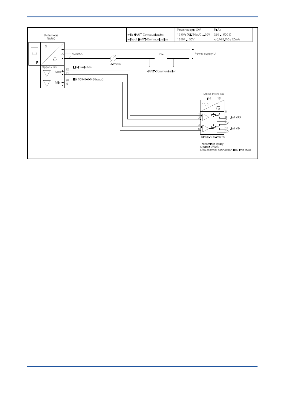
Fig. 3-7 RAMC 2-wire unit with HART-communication, with limit switches and transmitter relay
See also other documents in the category Yokogawa Sensors:
- EJA438 (5 pages)
- EJA120A (6 pages)
- EJA115 (85 pages)
- EJA120A (47 pages)
- EJA120A (79 pages)
- EJA130A (2 pages)
- EJA130A (4 pages)
- EJA120A (31 pages)
- EJA130A (47 pages)
- EJA120A (40 pages)
- EJA210A (70 pages)
- EJA130A (4 pages)
- EJA430A (78 pages)
- EJA210E (96 pages)
- EJA210E (52 pages)
- EJA210E (89 pages)
- EJA210E (170 pages)
- EJX120A (4 pages)
- EJA210E (9 pages)
- EJX115A (55 pages)
- EJA210E (41 pages)
- EJX910A (83 pages)
- EJX910A (9 pages)
- EJX910A (103 pages)
- FlowNavigator Software (163 pages)
- EJX910A (55 pages)
- EJX910A (175 pages)
- EJA530A (67 pages)
- EJA120A (83 pages)
- EJX530A (52 pages)
- EJA110E (85 pages)
- EJA110E (4 pages)
- EJX120A (85 pages)
- EJA118 (76 pages)
- EJX118A (64 pages)
- EJA438 (72 pages)
- EJA430E (85 pages)
- EJX430A (40 pages)
- EJX430A (76 pages)
- EJA430E (7 pages)
- EJX430A (6 pages)
- EJA430E (41 pages)
- EJA430E (96 pages)
- EJX438A (10 pages)
- ADMAG AXR (194 pages)