Installation, 1 installation in the pipeline, Installation -1 – Yokogawa RAMC User Manual
Page 17: 1 installation in the pipeline -1
<3. INSTALLATION>
3-1
IM 01R01B02-00E-E 10th edition January 01, 2013 -00
All Rights Reserved. Copyright © 2003, Rota Yokogawa
3. Installation
3.1 Installation in the pipeline
Be sure to remove the transport lock card-board strip from the measuring tube. Check that no cardboard
remains in the tube.
The RAMC flow rate meter must be installed in a vertical pipeline, in which the medium flows upwards. The
vertical position has to be checked at the outer edge of the flanges. Bigger nominal diameters (DN80/DN100)
require straight pipe sections of at least 5D in front and behind the RAMC.
The nominal diameter of the RAMC should correspond to the nominal diameter of the pipeline.
To avoid stress in the connecting pipes, the connecting flanges must be aligned in parallel and axial direction.
Bolts and gaskets have to be selected according to the maximum operating pressure, the temperature range
and corrosion conditions. Centre gaskets and tighten nuts with a torque appropriate for the pressure range.
If contamination or soiling of the RAMC is to be expected, a bypass should be installed to allow the removal of
the instrument without interruption of the flow.
Please read also chapter 2.2. For further instructions on installation please refer to VDI/VDE3513.
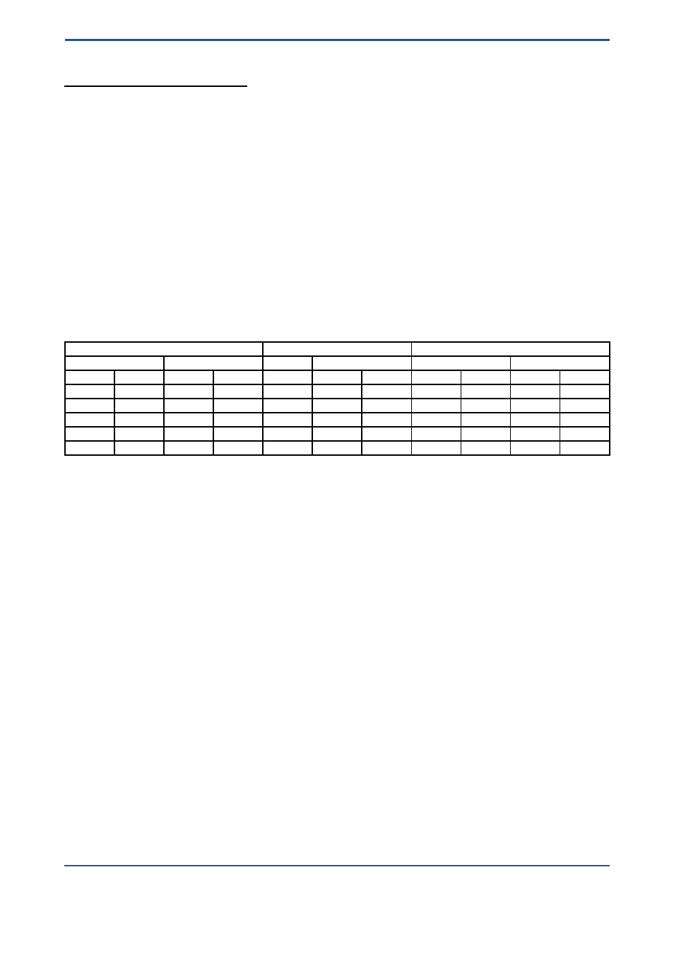
Tightening the flange threads for RAMC with PTFE- liner with the following torques:
Nominal Size
Bolts
Maximum Torque
EN 1092-1
ASME B 16.5
EN 1092-1
ASME
EN 1092-1
ASME 150 lbs
DN
PN
Inches
lbs
150 lbs
300 lbs
Nm
ft*lbf
Nm
ft*lbf
15
40
½
150/300 4 x M12
4 x ½´´
4 x ½´´
9.8
7.1
5.2
3.8
25
40
1
150/300 4 x M12
4 x ½´´
4 x ½´´
21
15
10
7.2
50
40
2
150/300 4 x M16 4 x 5/8´´ 8 x 5/8´´
57
41
41
30
80
16
3
150/300 4 x M16 4 x 5/8´´
8 x ¾´´
47
34
70
51
100
16
4
150/300 4 x M16 8 x 5/8´´
8 x ¾´´
67
48
50
36