4 dimensions, 4 dimensions -9 – Yokogawa EJA310A User Manual
Page 68
IM 01C21D01-01E
10-9
10. GENERAL SPECIFICATIONS
10.4
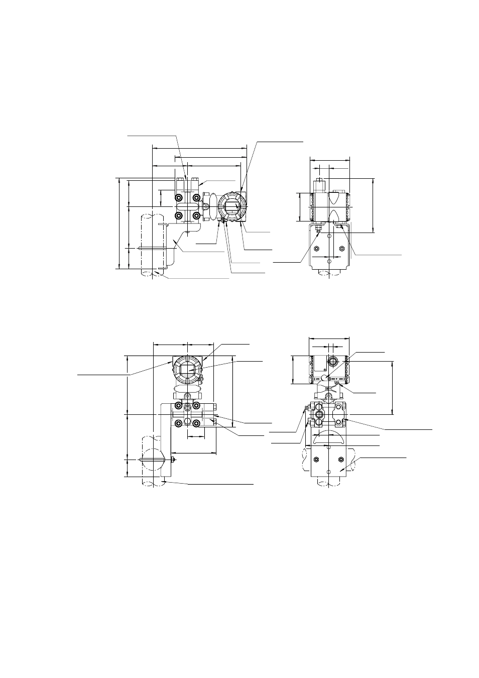
Dimensions
᭹ Model EJA310A and EJA430A
Vertical Impulse Piping Type
Process connector upside (INSTALLATION CODE ‘6’) (For CODE ‘2’, ‘3’ or ‘7’,
refer to the notes below.)
72
(2.83)
102
(4.02)
53
( 2.09)
234(9.21)
259(10.20)
197 (7.76)
97
(3.82)
146 (5.75)
46
(1.81)
External indicator
conduit connection
Blind plug
(Optional)
Ground
terminal
Mounting bracket
(L-type, Optional)
Conduit
connection
Internal
indicator
(Optional)
Zero
adjustment
Shrouding bolt
(Note 4)
Process connector
(Optional)
Process
connections
12
(0.47)
27
(1.06)
148
(5.83)
ø78
(3.07)
110 (4.33)
2-inch pipe (O.D. 60.5mm)
Vent/Drain
plugs
High
pressure
side (Note 1)
Low
pressure
side
Terminal
side
Open to
atmosphere (Note 3)
(ø9mm)
F1002.EPS
Horizontal Impulse Piping Type
(INSTALLATION CODE ‘9’) (For CODE ‘8’, refer to the notes below.)
94
(3.70)
72
(2.83)
197
(7.76)
46
(1.81)
125 (4.92)
162
(6.38)
124
(4.88)
47
(1.85)
External indicator
conduit connection
Blind plug
(Optional)
Conduit
connection
Process
connector
(Optional)
2-inch pipe (O.D. 60.5mm)
Internal
indicator
(Optional)
Process
connection
Zero
adjustment
Ground
terminal
Vent plugs
Drain plugs
High
pressure
side (Note 1)
Low
pressure
side
Terminal
side
64
(2.52)
ø78
(3.07)
146
(5.75)
27 (1.06)
110 (4.33)
12
(0.47)
Open to
atmosphere (Note 3)
(ø5mm)
Mounting bracket
(Flat-type, Optional)
F1003.EPS
Note 1: When INSTALLATION CODE ‘2’, ‘3’ or ‘8’ is selected, high and low pressure side on above
figure are reversed.
(i. e. High pressure side is on the left side.)
Note 2: When INSTALLATION CODE ‘3’ or ‘7’ is selected, process connetion and mounting bracket on
above figure are reversed.
Note 3: Applicable for EJA430A.
Note 4: Applicable only for ATEX and IECEx Flameproof type.