13) span adjustment, 13)span adjustment -14 – Yokogawa EJA310A User Manual
Page 47
IM 01C21D01-01E
8-14
8. BRAIN TERMINAL BT200 OPERATION
(c) Zero Point Adjustment Using the External Zero
Adjustment Screw
• Enabling/inhibiting of zero point adjustment using
the external zero-adjustment screw on the transmitter
(J20: EXT ZERO ADJ)
Follow the procedure below to enable or inhibit zero
point adjustment from the zero-adjustment screw on
the transmitter.
This is set to “ENABLE” when the instrument is
shipped.
• Example: Inhibiting zero adjustment by the
external zero-adjustment screw
ESC
SET
J20:EXIT ZERO ADJ
ENABLE
< ENABLE >
< INHIBIT>
Use the or key to
select “INHIBIT.”
Press the key twice to
enter the setting.
F0831.EPS
• Zero point adjustment using external zero-adjust-
ment screw on the transmitter
Turn the zero-adjustment screw on the outside of the
transmitter case using a slotted screwdriver. Turn the
screw to the right to increase the zero point or to the
left to decrease the zero output; the zero adjusts in
increments of 0.01% of the range setting.
Note that the amount of adjustment to the zero point
changes according to the speed at which the screw is
turned. To make fine adjustments, turn the screw
slowly; to make coarse adjustments, turn the screw
quickly.
Note: When a zero point adjustment has been made, do not turn
off the transmitter less than 30 seconds after adjustment.
(13) Span Adjustment
Each DPharp EJA series transmitter is factory
characterized according to the specification. Mount-
ing position effects or zero shifts caused by static
pressure are typically compensated by a zero adjust-
ment.
A span adjustment is a function to correct the slope
error from a zero point in characterizing 100% point
(HRV). This function can be used when span drifts
may be caused or characterization to the specific
pressure standard is required.
Therefore, the zero point adjustment should always
be performed before the upper point adjustment in
order to maintain the pitch between zero and 100%
points within the calibration range.
You can manually perform the trimming procedure
by using J15: SPAN ADJ.
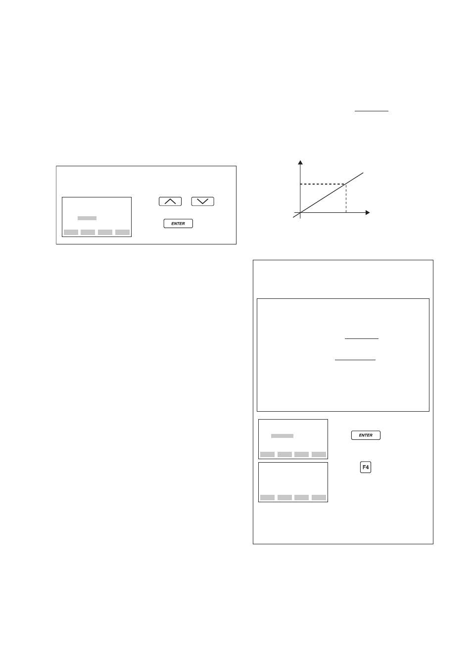
• Span adjustment value
The span adjustment value is calculated as follows.
Span adjustment value (%) =
P
1
: Actual differential pressure/pressure value
A40: Input (indicated as the value after zeroing)
Measurement pressure
Applied pressure
P
1
Ϫ A40
P
1
ϫ
100
A40
P
1
0
F0846.EPS
• Example: For the range of 0 to 30 kPa.
A40: INPUT = 30.15 kPa
J15: SPAN ADJ = 0.15 %
Suppose that a standard pressure of 30 kPa is applied and
the value of the parameter of A40: INPUT is 30.15 kPa.
Firstly, obtain the slope error for the span as follows;
Add
Ϫ0.5% to 0.15% of the current value to calculate the
accumulated span adjustment value.
0.15
ϩ (Ϫ0.50) = Ϫ0.35
F0847.EPS
FEED
NO
OK
SET
J15:SPAN ADJ
-0.35 %
ESC
CLR
DEL
SET
J15:SPAN ADJ
0.15 %
- 0.35
Set
Ϫ0.35.
Press key twice.
Press the (OK) key.
30.00
Ϫ30.15
30.00
ϫ 100 = Ϫ0.5 (%)
ϭ
Span adjustment value (%) =
Note: Enter 0.00 to J15: SPAN ADJ to reset the
span adjustment to the initial value at the
shipment.
P
1
Ϫ
A40
P
1
ϫ100