Yokogawa EJA310A User Manual
Page 61
IM 01C21D01-01E
10-2
10. GENERAL SPECIFICATIONS
Supply Voltage “
᭛”:
10.5 to 42 V DC for general use and flameproof type
10.5 to 32 V DC for lightning protector (Optional code /A)
10.5 to 30 V DC for intrinsically safe, Type n,
nonincendive, or non-sparking type
Minimum voltage limited at 16.4 V DC for digital
communications, BRAIN and HART
EMC Conformity Standards “
᭛”:
,
EN61326-1 Class A, Table 2 (For use in industrial
lications)
EN61326-2-3
Communication Requirements “
᭛”:
BRAIN
Communication Distance;
Up to 2 km (1.25 miles) when using CEV polyethyl-
ene-insulated PVC-sheathed cables.
Communication distance varies depending on type
of cable used.
Load Capacitance;
0.22 µF or less (see note)
Load Inductance;
3.3 mH or less (see note)
Input Impedance of communicating device;
10 kΩ or more at 2.4 kHz.
Note: For general-use and Flameproof type.
For Intrinsically safe type, please refer to
‘Optional Specifications.’
HART
Communication Distance;
Up to 1.5 km (1 mile) when using multiple twisted
pair cables. Communication distance varies
depending on type of cable used.
Use the following formula to determine cable
length for specific applications:
L=
-
65 x 10
6
(R x C)
(C
f
+ 10,000)
C
-40
(-40)
0
(32)
40
(104)
80
(176)
120 (248)
0.1{0.75}
0.13{1}
1{7.5}
100{750}
10{75}
2.7{20}
0.46
{3.45}
0.01{0.075}
0.013{0.1}
85
(185)
{mmHg abs}
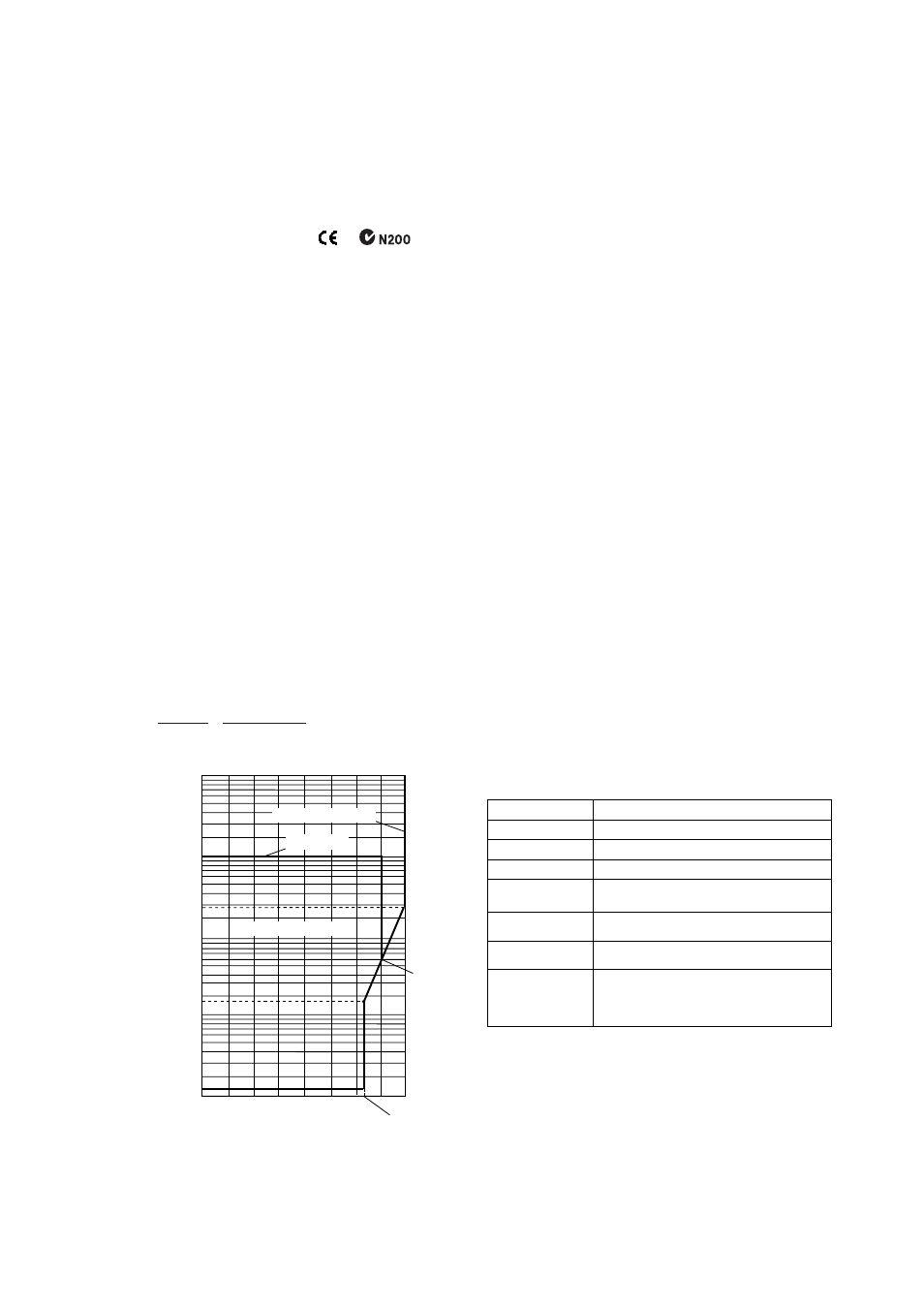
Working
pressure
kPa abs
Applicable range
Process temperature °C(°F)
M and A capsule
L capsule
F1001.EPS
Figure 1. Working Pressure and Process Temperature
Where:
L = length in meters or feet
R = resistance in Ω (including barrier resistance)
C = cable capacitance in pF/m or pF/ft
C
f
= maximum shunt capacitance of receiving
devices in pF/m or pF/ft
᭹ Physical Specifications
Wetted Parts Materials:
Diaphragm, Cover flange, Process connector and
Drain/Vent Plug;
See ‘Model and Suffix Codes’
Capsule Gasket;
Teflon-coated SUS316L
Process Connector Gasket;
PTFE Teflon (EJA310A and EJA430A)
Fluorinated Rubber (EJA310A and EJA430A with
Optional code /N2 and /N3 and EJA440A with
Capsule code C)
Glass reinforced Teflon (EJA440A with Capsule
code D)
Non-wetted Parts Materials:
Bolting;
SCM435, SUS630, or SUH660
Housing;
Low copper cast-aluminum alloy with polyurethane
paint (Munsell 0.6GY3.1/2.0)
Degrees of Protection
IP67, NEMA4X, JIS C0920 immersion proof
Cover O-rings;
Buna-N
Data plate and tag;
SUS304 or SUS316 (optional)
Fill Fluid;
Silicone or Fluorinated oil (optional)
Weight:
3.9 kg (8.6 lb) without mounting bracket or process
connector (EJA430A)
Connections:
Refer to the ‘Model and Suffix Codes’ to specify
the process and electrical connection type.
< Settings When Shipped > “
᭛”
Tag Number
Output Mode
Display Mode
Operation Mode
Damping Time
Constant
As specified in order
*1
‘Linear’
‘2 sec.’
‘Normal’ unless otherwise specified in order
‘Linear’
Calibration Range
Units
*2
As specified in order
As specified in order
Selected from mmH
2
O, mmAq, mmWG,
mmHg, Pa, hPa, kPa, MPa, mbar, bar,
gf/cm
2
, kgf/cm
2
, inH
2
O, inHg, ftH
2
O, or psi.
(Only one unit can be specified)
Calibration Range
Higher Range Value
Calibration Range
Lower Range Value
T1005.EPS
*1:
Up to 16 alphanumeric characters (including - and
· ) will be entered in the amplifier memory.
*2:
The units are in absolute terms for EJA310A, and
Torr, psia, or atm is also available.