Operation, 1 preparation for starting, Operation -1 – Yokogawa EJA310A User Manual
Page 29: Preparation for starting operation -1, 1 preparation for starting operation
IM 01C21D01-01E
7-1
7. OPERATION
7.
OPERATION
7.1 Preparation for Starting
Operation
The Model EJA310A, EJA430A and EJA440A
pressure transmitter measures the pressure of liquids,
gases, and steam. This section describes the operation
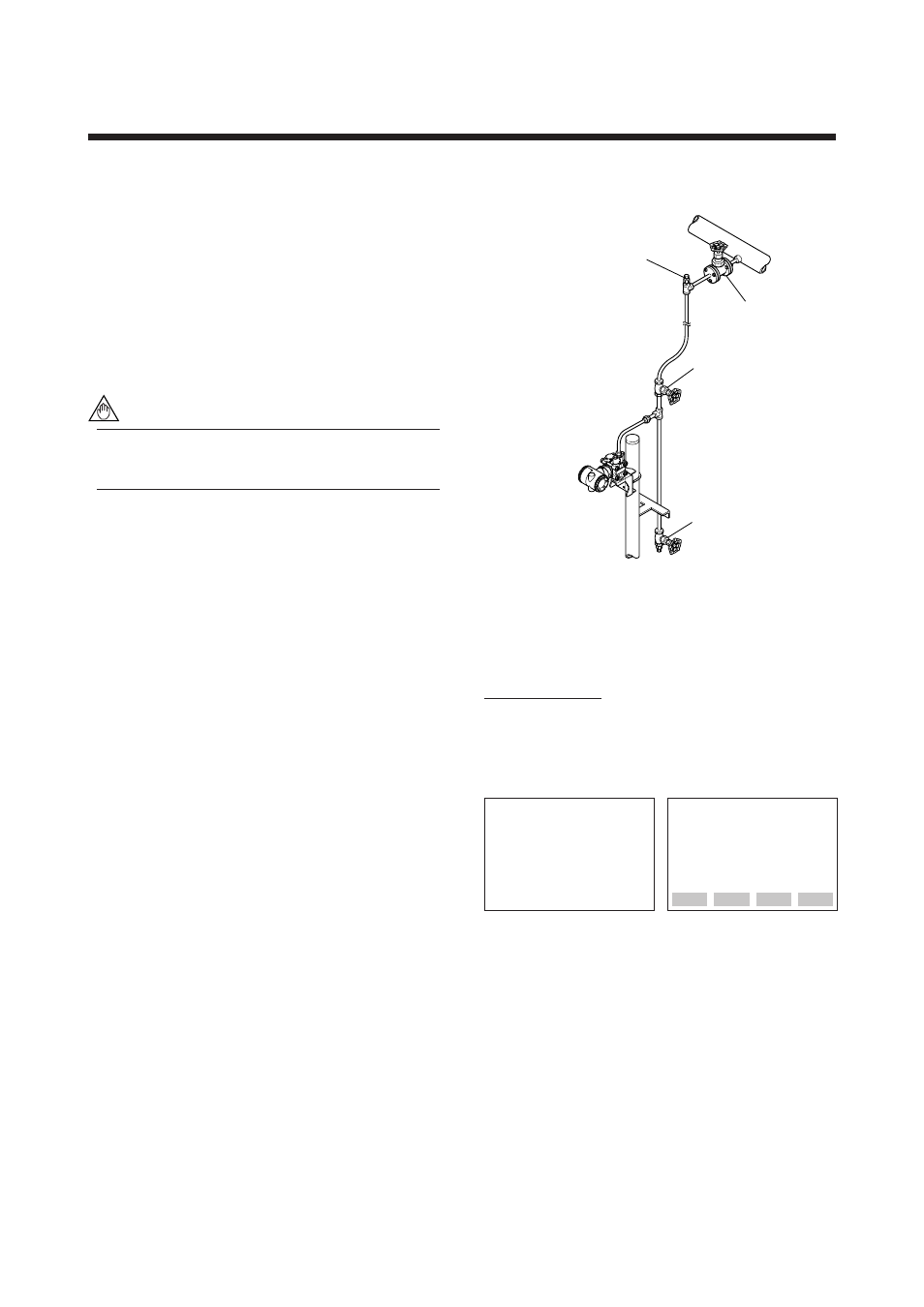
procedure for the EJA430A as shown in Figure 7.1
(vertical impulse piping type, high-pressure connection:
right side) when measuring a pressure.
NOTE
Confirm that the process pressure tap valve,
drain valve, and stop valve are closed.
(a) Introduce a process fluid into the impulse piping
and then to the transmitter in the following proce-
dure:
1) Open the tap valve (main valve) to fill the impulse
piping with process fluid.
2) Gradually open the stop valve to introduce process
fluid into the transmitter pressure-detector section.
3) Confirm that there is no pressure leak in the
impulse piping, transmitter, or other components.
(b) Venting Gas from the Transmitter Pressure-detector
Section
Since the piping in the example of Figure 7.1 is
constructed to be self-venting, no venting operation
is required. If it is not possible to make the piping
self-venting, refer to Subsection 7.5 for instructions.
(c) Turn ON power and connect the BT200.
Open the terminal box cover, and connect the
BT200 to the SUPPLY + and – terminals.
(d) Using the BT200, confirm that the transmitter is
operating properly. Check parameter values or
change the setpoints as necessary. See Chapter 8 for
BT200 operation.
If the transmitter is equipped with an integral
indicator, its indication can be used to confirm that
the transmitter is operating properly.
Vent plug (Fill plug)
Tap valve
Stop valve
Drain valve
F0701.EPS
Figure 7.1 Liquid Flow Measurement
Confirming that Transmitter is Operating
Properly
Using the BT200
• If the wiring system is faulty, ‘communication error’
appears on the display.
• If the transmitter is faulty, ‘SELF CHECK ERROR’
appears on the display.
communication error
PARAM
C60:SELF CHECK
ERROR
Communication error
(Faulty wiring)
Self-diagnostic error
(Faulty transmitter)
DATA
DIAG
PRNT
ESC
F0702.EPS