7) unit setup for displayed temperature, 8) operation mode setup, 9) output status display/setup when a cpu failure – Yokogawa EJA310A User Manual
Page 44
IM 01C21D01-01E
8-11
8. BRAIN TERMINAL BT200 OPERATION
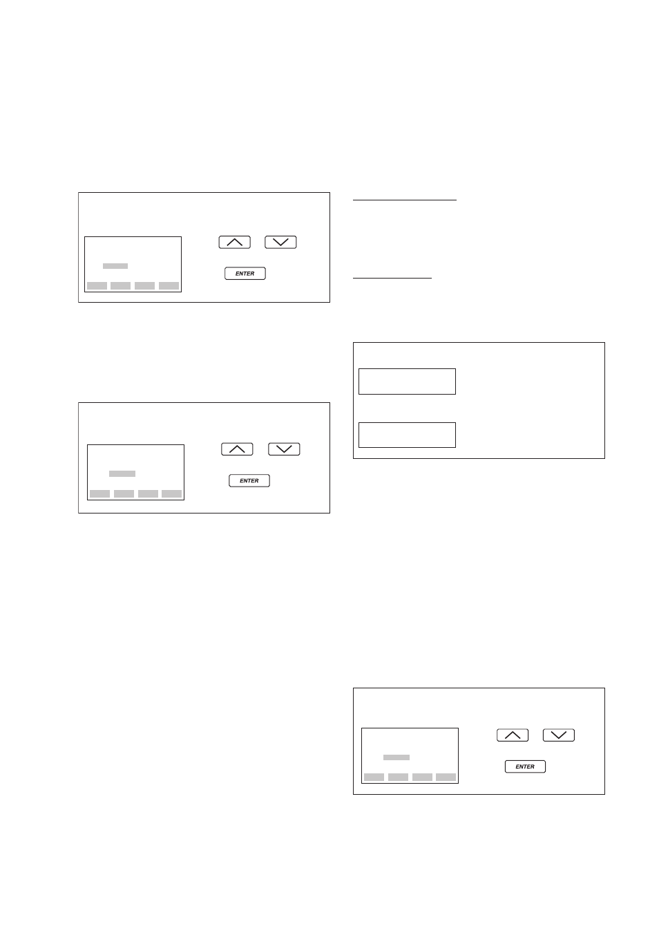
(7) Unit Setup for Displayed Temperature
(D30: TEMP UNIT)
When the instrument is shipped, the temperature units
are set to degC. Follow the procedure below to
change this setting. Note that changing the unit here
changes the unit for A20: AMP TEMP (amplifier
temperature) and A21: CAPSULE TEMP (capsule
temperature).
• Example: Change the unit for the temperature
display.
ESC
SET
D30:TEMP UNIT
deg C
< deg C >
< deg F >
Use the or key to
select “deg F.”
Press the key twice to
enter the setting.
F0822.EPS
(8) Operation Mode Setup
(D40: REV OUTPUT)
This parameter allows the direction of the 4 to 20
mA output to be reversed with respect to input.
Follow the procedure below to make this change.
• Example: Change 4 to 20 mA output to 20 to
4 mA output.
ESC
SET
D40:REV OUTPUT
NORMAL
< NORMAL >
< REVERSE>
Use the or key
to select REVERSE.
Press the key twice to
enter the setting.
F0823.EPS
(9) Output Status Display/Setup when a CPU
Failure (D52: BURN OUT)
This parameter displays the status of 4 to 20 mA DC
output if a CPU failure occurs. In case of a failure,
communication is disabled.
Setting of HIGH or LOW is enabled. This is done
with the pin (CN4) on the CPU assembly. See
Chapter 3 for details.
Standard specifications
The parameter is set to HIGH. If a failure, the
transmitter outputs the signal of 110% or higher. The
parameter D53: ERROR OUT is set to HIGH from
the factory.
Optional code/C1
The parameter is set to LOW. If a failure, output
which is –5% or lower is generated. The parameter
D53: ERROR OUT is set to LOW from the factory.
• Example: Standard specifications
pin (CN4) position: H
D52: BURN OUT
HIGH
F0824.EPS
• Example: Optional code/C1
pin (CN4) position: L
D52: BURN OUT
LOW
(10) Output Status Setup when a Hardware
Error Occurs (D53: ERROR OUT)
This parameter allows the setting of the output status
when a hardware error occurs. The following three
selections are available.
(a) HOLD; Outputs the last value held before the
error occurred.
(b) HIGH; Outputs an output of 110% when an error
has occurred.
(c) LOW; Outputs an output of –5% when an error
has occurred.
Note: A hardware error means CAP MODULE FAULT of Er.01 or
AMP MODULE FAULT of Er. 02 which are shown in 8.5.2
“Errors and Countermeasures.”)
• Example: Set the output status to LOW when
a hardware error occurs.
ESC
SET
D53:ERROR OUT
HIGH
< HIGH>
< LOW>
< HOLD>
Use the or key
to select “LOW.”
Press the key twice to
enter the setting.
F0825.EPS