2 zero point adjustment, Zero point adjustment -2 – Yokogawa EJA310A User Manual
Page 30
IM 01C21D01-01E
7-2
7. OPERATION
Using the integral indicator
• If the wiring system is faulty, the display stays blank.
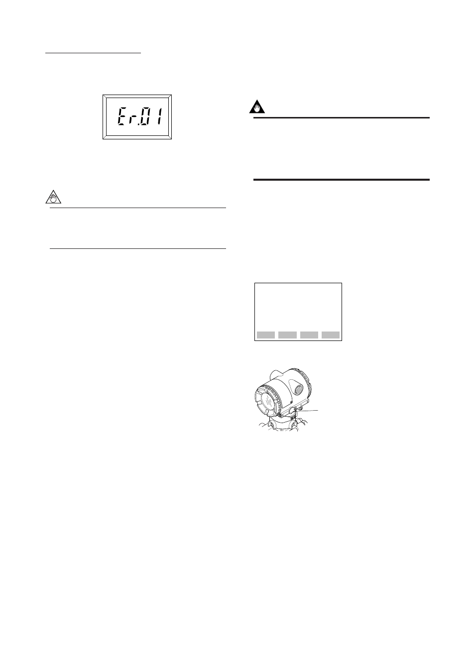
• If the transmitter is faulty, an error code will appear
on the display according to the nature of the error.
Self-diagnostic error on
the integral indicator
(Faulty transmitter)
F0703.EPS
NOTE
If any of the error indications above appears on
the display of the integral indicator or BT200,
refer to Subsection 8.5.2 for corrective action.
Verify and Change Transmitter Parameter
Setting and Values
The following parameters are the minimum settings
required for operation. The transmitter has been
shipped with these parameters. To confirm or change
the values, see Subsection 8.3.3.
• Measuring range..........See Subsection 8.3.3 (2)
• Operation mode...........See Subsection 8.3.3 (7)
7.2 Zero Point Adjustment
Adjust the zero point after operating preparation is
completed.
IMPORTANT
Do not turn off the power to the transmitter
immediately after a zero adjustment. Powering
off within 30 seconds after a zero adjustment will
return the adjustment back to the previous
settings.
The zero point adjustment can be made in either way:
using the zero-adjustment screw of the transmitter or
the BT200 operation.
For output signal checking, display the parameter A10:
OUTPUT (%) in the BT200.
Output signal (%)
display
PARAM
A10:OUTPUT(%)
0.0 %
A11:ENGR OUTPUT
A20:AMP TEMP
DATA
DIAG
PRNT
ESC
F0704.EPS
Zero-adjustment
screw
᭹BT200
᭹Zero-adjustment Screw
After reviewing this parameter you are prepared to
adjust the zero point. When making the zero adjust-
ment on a pressure transmitter, the process pressure
value does not have to be set to the low limit of the
measurement range (0%). In such case, adjust the
transmitter output signal to the actual measured value
obtained from a high-accuracy pressure measuring
instrument.