Indication and input pressure indication, User-set engineering unit display – Yokogawa EJA310A User Manual
Page 43
IM 01C21D01-01E
8-10
8. BRAIN TERMINAL BT200 OPERATION
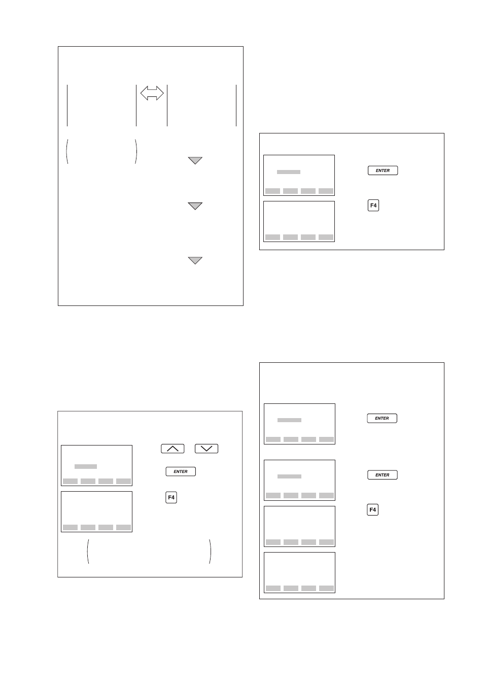
% indication and
input pressure
indication
Transmitter is set
for “% display” when
shipped.
D20: DISP SELECT
NORMAL %
INP PRES
PRES & %
User-set engineering
unit display
D20: DISP SELECT
USER SET
USER & %
D21: DISP UNIT
D22: DISP LRV
D23: DISP HRV
Set for user-set
engineering unit display.
Set a unit to be
displayed on the BT200.
Set a numeric value for
engineering unit for 4 mA
output (LRV).
Set a numeric value for
engineering unit for 20 mA
output (HRV).
F0818.EPS
a. Display Selection (D20: DISP SELECT)
Follow the instructions given to the below to change
the range of integral indication scales.
When USER SET is selected, the user set values of
integral indication and A11: ENGR. OUTPUT
parameter are indicated.
• Example: Set the integral indicator scale to
engineering units display.
The “%” disappears from the
integral indicator display.
ESC
SET
D20:DISP SELECT
USER SET
FEED
NO
OK
SET
D20:DISP SELECT
NORMAL %
Use the or key
to select “USER SET.”
Press the key twice to
enter the setting.
Press the (OK) key.
F0819.EPS
b. Setting User-set Engineering Unit
(D21: DISP UNIT)
This parameter allows entry of the engineering units
to be displayed on the BT200. When the instrument
is shipped, this is set as specified in the order.
Follow the procedure below to change this setting.
This parameter need not be set for % display.
• Example: Set an engineering unit M.
CODE
CAPS
CLR
ESC
SET
D21:DISP UNIT
M
FEED
NO
OK
SET
D21:DISP UNIT
M_
Set “M.”
Press the key twice to
enter the setting.
Press the (OK) key.
F0820.EPS
c. Lower and Higher Range Value Setup
in Engineering Unit (D22: DISP LRV,
D23: DISP HRV)
These parameter items are used to set the lower and
higher range values for the engineering unit display.
When the instrument is shipped, these are set as
specified in the order. Follow the procedure below to
change these settings. Note that these parameters
need not be set for % display.
• Example: Set lower range value (LRV) to –50
and higher range value (HRV) to 50.
FEED
NO
OK
SET
D23:DISP HRV
50M
Press the (OK) key.
F0821.EPS
DEL
CLR
ESC
DATA
DIAG
PRNT
ESC
PARAM
D21:DISP UNT
M
D22:DISP LRV
– 50M
D23:DISP HRV
50M
DEL
CLR
ESC
SET
D22:DISP LRV
0M
- 50
Set “–50.”
Press the key twice to
enter the setting.
Setting LRV
Setting HRV
Set “50.”
Press the key twice to
enter the setting.
SET
D23:DISP HRV
100M
+ 50