13) bi-directional flow measurement setup, 14) range change while applying actual inputs – Yokogawa EJA440E User Manual
Page 21
<3. Operation>
3-13
IM 01C25T03-01E
(12) Output Status Setup when a Hardware
Error Occurs
(D26: ERROR OUT)
This parameter allows the setting of the output
status when a hardware error occurs. The following
selections are available.
(a) BURNOUT DIR; Outputs the corresponding
values of 110% or –5% of output signals
according to the setting by burnout direction
switch (BO) on the CPU board.
(b) HOLD; Outputs the last value held before the
error occurred.
Note: A hardware error means CAP.ERR of AL.01 or AMP.ERR
of AL.02 which are shown in table 4.1 Alarm Message
Summary.
• Example: Set the output status to
HOLD when
a hardware error occurs.
ESC
SET
D26:ERROR OUT
BURNOUT DIR
< BURNOUT DIR >
< HOLD >
Use the or key
to select
HOLD.
Press the key twice to
enter the setting.
F0331.ai
Then press the (OK) key.
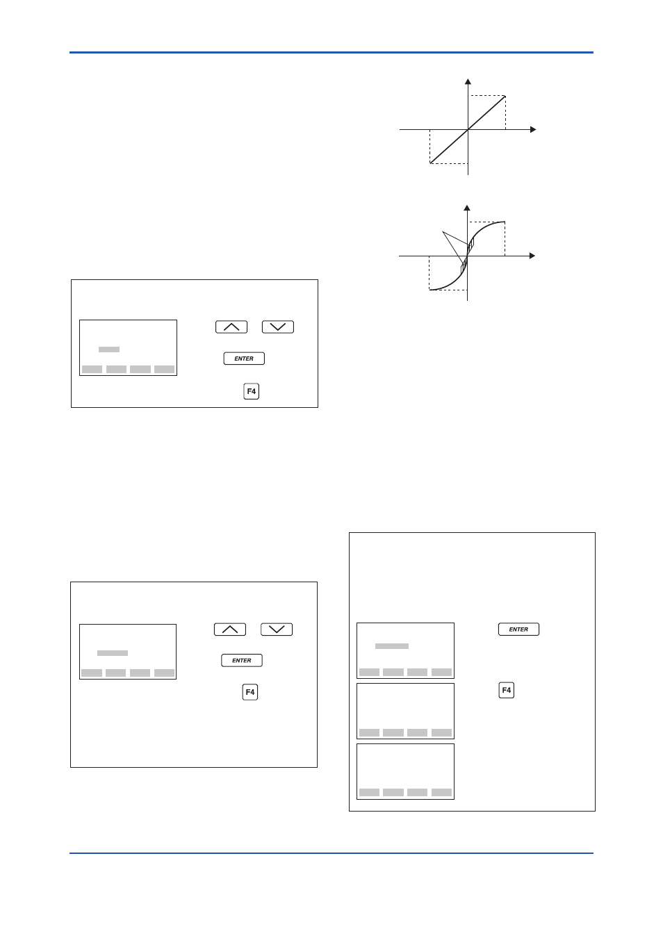
(13) Bi-directional Flow Measurement
Setup
(E30: BI DIRE MODE)
(a) This parameter enables selection of 50% output
at an input of 0 kPa.
Procedure is shown in the figure below.
(b) Combining this with
C40: OUTPUT MODE
provides a square root output computed
independently for 0% to 50% output and for
50% to 100% output.
• Example: If measurement range is 0 to 10 kPa
(LRV=0 kPa, URV=10 kPa)
The measurement range changes to –10 to 0 to 10 kPa
(output 0% to 50% to 100).
Note that
C21: PRES LRV and C22: PRES URV
are not changed.
ESC
SET
E30:BI DIRE MODE
OFF
< OFF >
< ON >
Use the or key
to select
ON.
Press the key twice to
enter the setting.
F0332.ai
Then press the (OK) key.
20 mA (100% display)
4 mA (–100% display)
● Output mode “LINEAR”
LRV
HRV
F0333.ai
20 mA (100% display)
Low Cut
4 mA (–100% display)
● Output mode “SQUARE ROOT”
LRV
HRV
(14) Range Change while Applying Actual
Inputs
(H10: AUTO P LRV, H11: AUTO P URV)
This feature allows the lower and upper range
values to be set up automatically with the actual
input applied. If the lower and upper range values
are set, C21: PRES LRV and C22: PRES URV are
changed at the same time.
Follow the procedure in the figure below.
The measurement span is determined by the upper
and lower range values. Changing the lower range
value results in the upper range value changing
automatically, keeping the span constant.
• Example 1: When changing the lower range
value to 0.5 kPa for the present
setting of 0 to 30 kPa, take the
following action with input pressure
of 0.5 kPa applied.
FEED
NO
OK
SET
H10:AUTO P LRV
0.5000 kPa
DATA
DIAG
PRNT
ESC
PARAM
H10:AUTO P LRV
0.5000 kPa
H11:AUTO P URV
30.500 kPa
H20:AUTO SP LRV
0.0 MPa
ESC
SET
H10:AUTO P LRV
0 kPa
+ 0
F0334.ai
The upper range value is changed
keeping the span constant.
Parameters
C21 and C22 are
changed at the same time.
Press the key twice.
The lower range value is changed
to 0.5 kPa.
Press the (OK) key.