Location of pins and ports for inputs and outputs, Wiring, Figure 9a — power wiring – Watlow series l rev g - 02-12-08.pdf User Manual
Page 9
Wa t l o w S e r i e s N 7
■
9
■
C h a p t e r 2 : I n s t a l l a n d W i r e
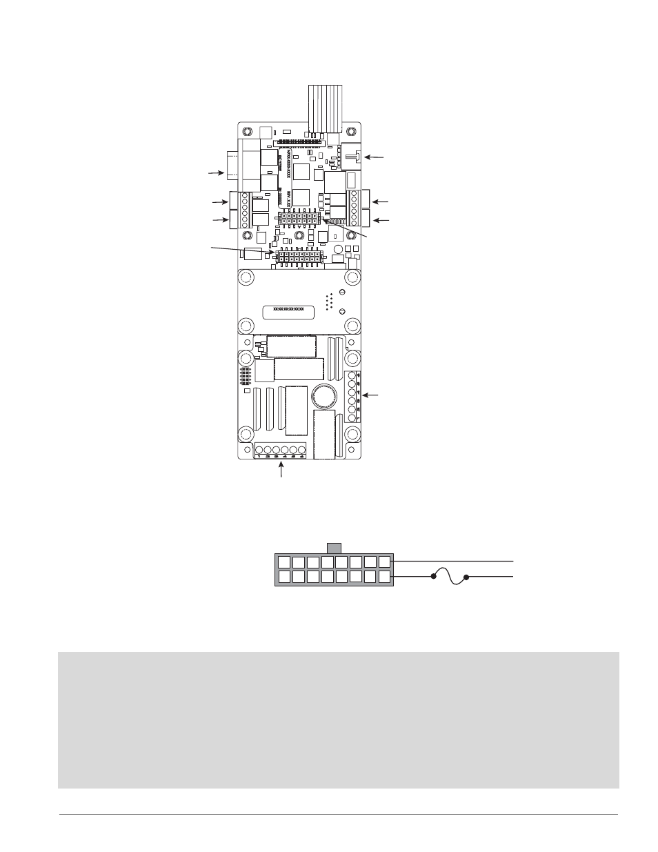
5-pin Master
Communications Port
Input 2
14 pins
9-pin Slave
Communications Port
Input 3
16 pins
1
2
3
4
5
6
6
5
4
3
2
1
Input 4
Power
Control Outputs 1 & 2
Event Inputs 1 to 4
Event Outputs 1 to 4
Input 1
Control Outputs 3 & 4
Process Outputs 1 & 2
Event Inputs 5 to 8
High Voltage Module
High-voltage
Control Outputs 1 to 3
High Voltage Module
High-voltage Control Outputs 4
High-voltage Event Outputs 5 & 6
Location of Pins and Ports for Inputs and Outputs
1
9
L2
L1
1
2
3
4
5
6
7
8
9
10
11
12
13
14
15
16
Figure 9a — Power Wiring
• Nominal voltage: 24VÅ (ac)
• Class 2 power source required.
Ó
Warning: Use National Electric (NEC) or other country-spe-
cific standard wiring and safety practices when wiring and
connecting this controller to a power source and to electri-
cal sensors or peripheral devices. Failure to do so may
result in damage to equipment and property, and/or injury
or loss of life.
Ó
Warning: If high voltage is applied to the 24VÅ (ac) input,
irreversible damage will occur.
Note:
To prevent ground loops, maintain isolation from input to
output when using switched dc or analog process outputs.
Use ungrounded thermocouples.