Slave communications, Master communications, Figure 20d — slave, cmc converter – Watlow series l rev g - 02-12-08.pdf User Manual
Page 20: Figure 20c — master, cmc converter, Figure 20b — slave, b&b converter, Figure 20a — master, b&b converter
C h a p t e r 2 : I n s t a l l a n d W i r e
■
2 0
■
Wa t l o w S e r i e s N 7
Ó
Warning: Use National Electric (NEC) or other country-spe-
cific standard wiring and safety practices when wiring and
connecting this controller to a power source and to electri-
cal sensors or peripheral devices. Failure to do so may
result in damage to equipment and property, and/or injury
or loss of life.
Note:
To prevent ground loops, maintain isolation from input to
output when using switched dc or analog process outputs.
Use ungrounded thermocouples.
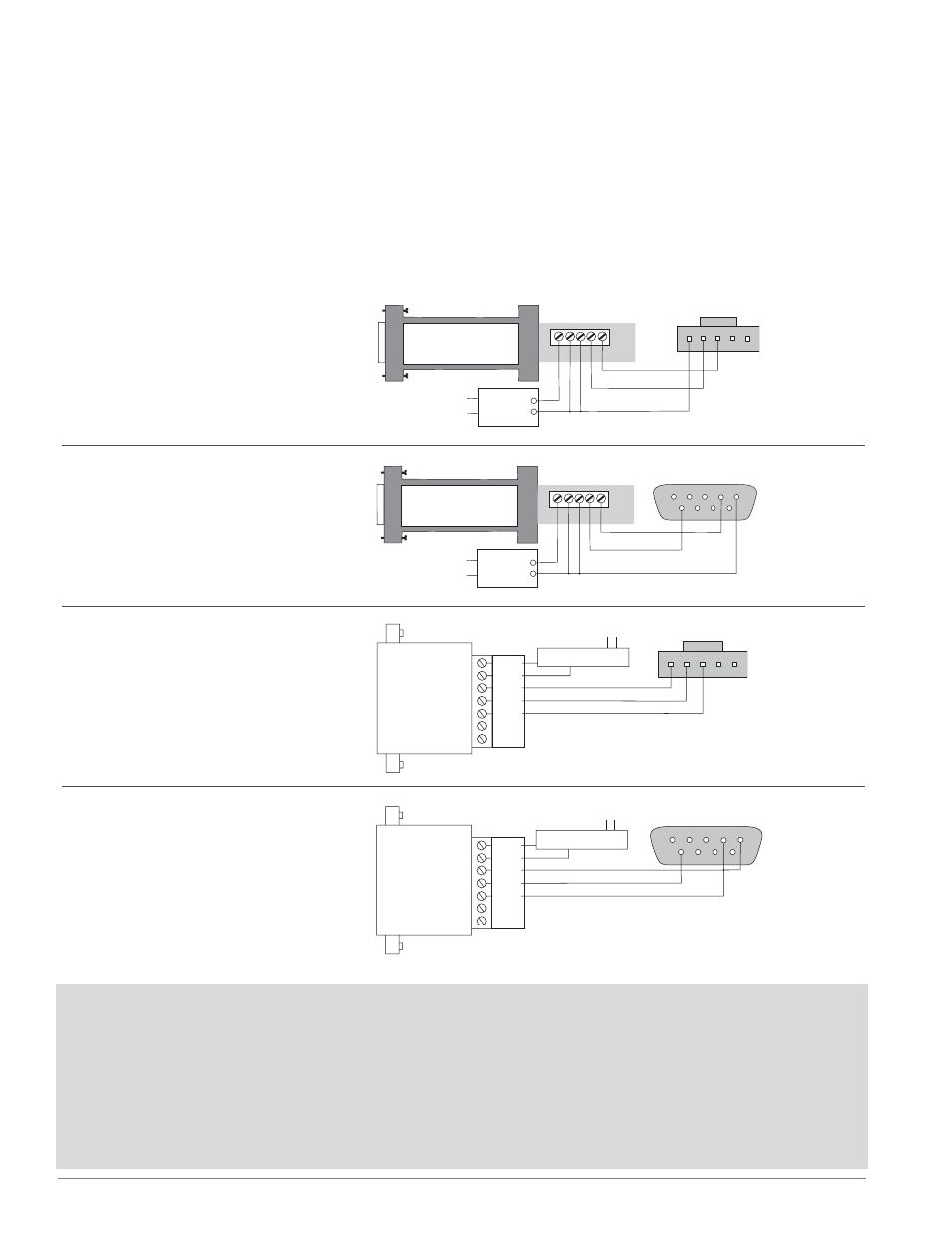
Communications using an EIA/TIA-232 to EIA/TIA-485 Converter
The circuit board illustration on page 9 shows the location of the master and slave ports.
1
2
3
4
5
6
7
8
9
9VÎ (dc) (see note)
120VÅ (ac)
COM.
T–/R–
T+/R+
EIA-232
ADA485L
EIA-485
A
B
A
B
G
9VÎ
G
DI/O
DI/O
4
6
0219-0217-0000
7-ft. comms cable
5
Figure 20d — Slave, CMC Converter
• RS-232: 19,200 or 9,600 baud
• RS-485: 9,600 baud
• 0 to 16 nodes
1
2
3
4
5
9VÎ (dc) (see note)
120VÅ (ac)
COM.
T–/R–
T+/R+
EIA-232
ADA485L
EIA-485
A
B
A
B
G
9VÎ
G
DI/O
DI/O
3
4
0219-0217-0000
7-ft. comms cable
5
Figure 20c — Master, CMC Converter
• 19,200 baud
• 0 to 16 nodes
• RS-485
1
2
3
4
5
6
7
8
9
T+/R+
TD (A)
TD (B)
T–/R–
120VÅ (ac)
Power
Supply
+
–
GND
4
6
485SD9TB
GND
12V
Î
(dc)
5
Figure 20b — Slave, B&B Converter
• RS-232: 19,200 or 9,600 baud
• RS-485: 9,600 baud
• 0 to 16 nodes
1
2
3
4
5
T+/R+
TD (A)
TD (B)
T–/R–
120VÅ (ac)
Power
Supply
+
–
GND
3
4
485SD9TB
GND
12V
Î
(dc)
5
Figure 20a — Master, B&B Converter
• 19,200 baud
• 0 to 16 nodes
• RS-485
Slave communications
The Series N7 can only respond to communications
on this port, as in the case of several N7s networked
to a Modbus master or a PC connected to this port to
monitor or adjust settings and process values. This is
how most Watlow controllers communicate.
Master communications
The Series N7 can initiate communications to con-
trollers networked on this port. An implementation
might include a custom modbus I/O board and mod-
bus motor control connected to the N7 master port
controlled by the N7's custom firmware.