Watlow series l rev g - 02-12-08.pdf User Manual
Page 24
A p p e n d i x
■
2 4
■
Wa t l o w S e r i e s N 7
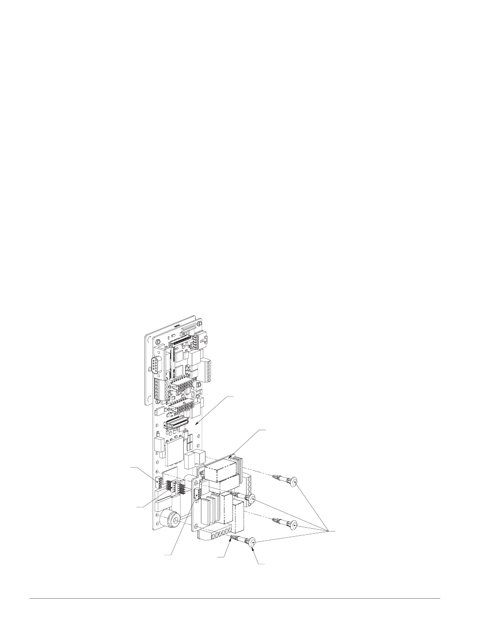
Install or Replace the Relay/High Voltage Output Module
(Z100-0817-000X)
Relay/High Voltage
Output Socket
Relay/High Voltage
Output Board
Sticking Header
Relay/High Voltage
Output Socket
Pointed End
Head
Circuit Board Spacer
Relay/High Voltage
Output Circuit Board
Main Circuit Board
1. Remove power from the controller.
2. Pre-assemble the circuit board spacers onto the
Relay/High Voltage Output circuit board.
•
Insert the pointed end of a circuit board spacer
into one of the four mounting holes of the
Relay/High Voltage Output circuit board from
the side of the circuit board that has the output
terminal blocks.
•
Using firm pressure, seat the circuit board spac-
er’s “head” onto the surface of the Relay/High
Voltage Output circuit board.
•
Repeat with the remaining three circuit board
spacers.
3. Pre-assemble the board stacking header onto the
Relay/High Voltage Output circuit board.
•
Align the pins of the board stacking header to
the socket on the Relay/High Voltage Output
circuit board. Make sure all pins are aligned
properly.
•
Using firm pressure insert the board stacking
header into the socket.
•
Make sure all pins of the board stacking header
are seated properly.
4. Install the Relay/High Voltage Output circuit board.
•
Align the pins of the board stacking header to
the socket on the main circuit board. Make sure
all pins are aligned properly.
•
Align the pointed end of the four circuit board
spacers with the four mounting holes on the
main circuit board.
•
While maintaining alignment of the pins of the
board stacking header and the circuit board
spacers, firmly press the Relay/High Voltage
Output circuit board onto the main circuit
board.
•
Verify that all pins of the board stacking header
and the circuit board spacers are seated proper-
ly.
5. Verify Output Wiring.
•
Install wiring to the appropriate output termi-
nals.
6. Test the Controller.
•
Reapply power to the controller and test.
Figure 24 — Install the Relay/High Voltage Output Module.