Install or replace the ethernet module – Watlow series l rev g - 02-12-08.pdf User Manual
Page 25
Wa t l o w S e r i e s N 7
■
2 5
■
A p p e n d i x
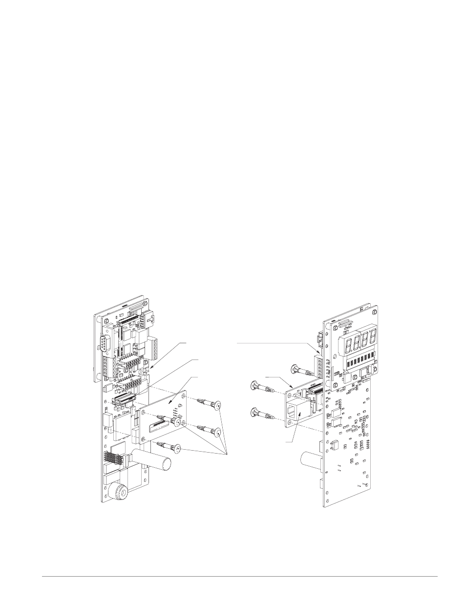
Install or Replace the Ethernet Module
(Z100-0816-0000)
Ethernet Module Connector
Ethernet Module Circuit Board
Circuit Board Spacer
N7 Main Circuit Board
RJ-485 Ethernet
Connector
1. Remove power from the controller.
2. Pre-assemble the circuit board spacers onto the
Ethernet circuit board.
• Insert the pointed end of a circuit board spacer
into one of the four mounting holes of the
Ethernet circuit board from the side of the cir-
cuit board that has the label on it.
• Using firm pressure seat the circuit board spac-
er until the head of the spacer is flush with the
surface of the Ethernet circuit board.
• Repeat with the remaining three circuit board
spacers.
3. Install the Ethernet circuit board.
• Align the Ethernet connector with the Ethernet
module connector.
• Align the pointed ends of the four circuit board
spacers with the four mounting holes on the
main circuit board.
• While maintaining alignment of the Ethernet
connectors and the circuit board spacers, firmly
press the Ethernet circuit board onto the main
circuit board.
• Verify that the Ethernet connector and the cir-
cuit board spacers are seated properly.
4. Verify Output Wiring.
• Install RJ-485 Ethernet connector.
5. Test the Controller.
• Reapply power to the controller and test.
Figure 25 — Install the Ethernet Module.