Process outputs, Figure 13b — process output 2, Figure 13a — process output 1 – Watlow series l rev g - 02-12-08.pdf User Manual
Page 13: Current, Volts
Wa t l o w S e r i e s N 7
■
1 3
■
C h a p t e r 2 : I n s t a l l a n d W i r e
Ó
Warning: Use National Electric (NEC) or other country-spe-
cific standard wiring and safety practices when wiring and
connecting this controller to a power source and to electri-
cal sensors or peripheral devices. Failure to do so may
result in damage to equipment and property, and/or injury
or loss of life.
Note:
To prevent ground loops, maintain isolation from input to
output when using switched dc or analog process outputs.
Use ungrounded thermocouples.
1
2
3
4
5
6
7
8
9
10
11
12 13
14
11
10
+
–
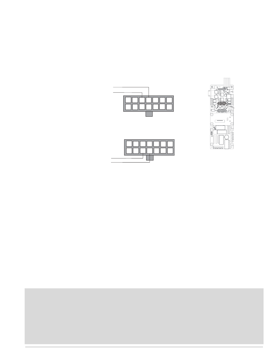
Figure 13b — Process Output 2
1
2
3
4
5
6
7
8
9
10
11
12 13
14
4
3
–
+
Figure 13a — Process Output 1
14 pins
Control Outputs 3 & 4
Process Outputs 1 & 2
Event Inputs 5 to 8
Process Outputs
Current
• 0 to 20 mA at 20V maximum
• Load: 1 k
Ω
maximum
Volts
• 0 to 10VÎ (dc) at 20 mA maximum
• Load: 500
Ω
minimum
- 12LS Controller (111 pages)
- 8LS Controller (140 pages)
- 8PID Controller (55 pages)
- Addendum to EZwarePlus (50 pages)
- ANASCAN (62 pages)
- ANASOFT (95 pages)
- ANAWIN 2 (154 pages)
- ANAWIN 3 (23 pages)
- Calibrating Watlow Series 988 Family Process Controls (19 pages)
- CAS (98 pages)
- CAS200 (124 pages)
- CLS (180 pages)
- CLS200 (251 pages)
- CLS200, MLS300 and CAS200 (92 pages)
- Control Console (12 pages)
- CPC400 (230 pages)
- DIN-A-MITE Style A (9 pages)
- DIN-A-MITE Style B (14 pages)
- DIN-A-MITE Style C (22 pages)
- DIN-A-MITE Style D (9 pages)
- DIN-Mount Adapter Instruction Sheet, Rev A (1 page)
- Dual DAC (4 pages)
- EM Gateway (28 pages)
- E-Safe Hybrid Relay Rev B (4 pages)
- E-SAFE II Hybrid Power Switch (4 pages)
- EZwarePlus Programming (264 pages)
- EZ-ZONE PM (111 pages)
- EZ-ZONE PM PID (125 pages)
- EZ-ZONE PM Express Limit (34 pages)
- EZ-ZONE PM Express (35 pages)
- EZ-ZONE PM Integrated Controller (181 pages)
- EZ-ZONE RM Limit Module Rev C (127 pages)
- EZ-ZONE RMA Modul (79 pages)
- EZ-ZONE RMC (236 pages)
- EZ-ZONE RME (124 pages)
- EZ-ZONE RMH (161 pages)
- EZ-ZONE RUI/Gateway (62 pages)
- EZ-ZONE RM-Scanner-Modul (140 pages)
- EZ-ZONE ST (97 pages)
- F4 External Event Board - Rev.B (2 pages)
- HG Series Mercury Displacement Relay (6 pages)
- LogicPro (296 pages)
- Mercury Relay or MDR Retrofit (13 pages)
- MICRODIN (106 pages)
- MICRODIN (24 pages)