Maple Systems MAP460D User Manual
Page 10
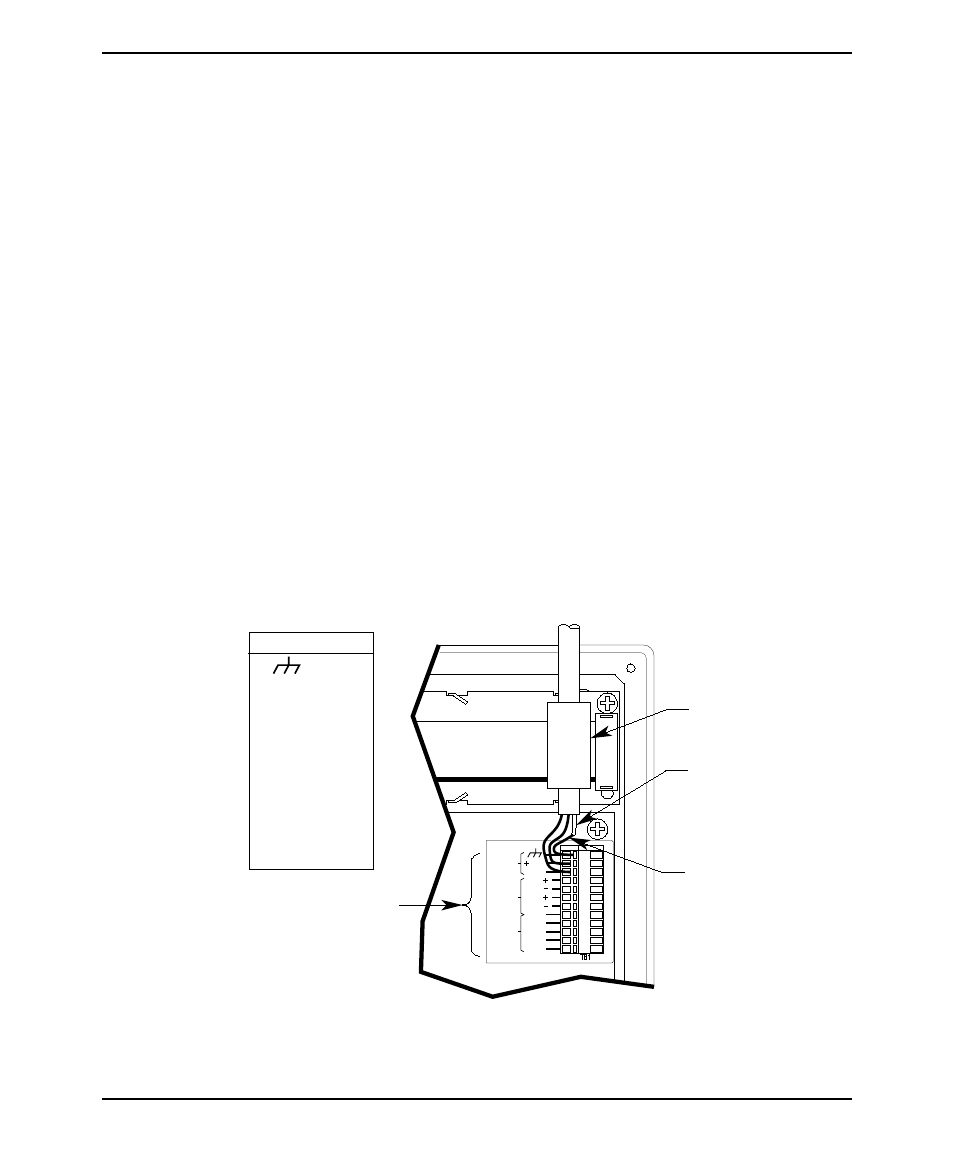
6. Connect the OIT operating cable wires to the terminal block. Refer to the
Assembly Instruction sheets included with the Maple Systems operating
cable or connector kit. Refer to Figure 5 for the MAP460D terminal block
pinout.
7. Pull out any slack from the OIT operating cable.
8. Rotate the rear of the OIT enclosure back into position while gently pulling
out the new slack generated in the cable as you proceed.
CAUTION: Due to the large size of the ferrite coil, it must be positioned very
carefully. Make sure that when the OIT enclosure halves are brought together, the
ferrite coil is positioned so there is no internal interference. The ferrite coil must be
positioned up against the inside wall of the OIT enclosure with the protruding OIT
operating cable kept short.
9. Tighten the cable strain relief nut.
10. Re-install the four screws into the back of the OIT enclosure
11. Route the operating cable to the PLC/host and connect.
12. Route the power pigtail to the OIT power supply.
13. Install the wires into the power supply as follows:
RED
+output
BLACK
-output
SHIELD
case ground.
10
MAP460D
1010-0093, REV 03
RS485
RS232
POWER
2
RXD
RTS
CTS
TXD
RXD
TXD
RTN
TXD
RXD
COM
24V
9
12
10
11
5
6
7
8
4
3
1
Heatshrink tubing
Chassis shield wire
Ferrite coil
Connection to
communication
wires of PLC/host
+24V
1
2
Function
Pin #
COM
3
RXD+
4
RXD-
5
TXD+
6
TXD-
7
RTN
8
RXD
9
TXD
10
CTS
11
RTS
12
Figure 5 Terminal Block Pinout Connection