Re-assembly – Ramsey Winch RPH-50000 SHORT DRUM W/AIR TENSIONER & 2-SPEED MOTOR User Manual
Page 14
12
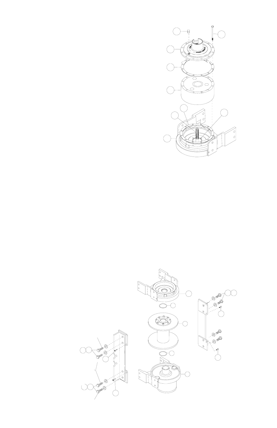
7. Remove (12) capscrews #17 to pull gear
housing cover and gasket from ring gear.
Remove input thrust washer, sun gear and
carrier assemblies from inside of ring gear.
Remove ring gear #4 and gasket #35 from
end bearing #10. Examine shifter shaft #12
for signs of wear, replace if necessary. Ex-
amine bushing #14 for signs of wear. Re-
place bushing, if necessary, by pressing old
bushing from housing and pressing new
bushing into place.
RE-ASSEMBLY
NOTE: DETERMINE MOUNTING CONFIGURATION OF WINCH (R.H. OR L.H.
MOUNTED) BEFORE ATTACHING TIE BARS TO WINCH. TO ASSURE PARTS
ARE MOUNTED TO PROPER SIDE, REFER TO WINCH MOUNTING CONFIGU-
RATIONS ON PAGE 17.
8. Seat well-oiled quad-ring #41 into groove of bushing in each end of drum
assembly #1. Carefully set drum assembly down over motor end bearing
#9. Lift gear-housing end bearing #10 and set into place on drum as-
sembly. Attach tie bars #2 and #3 using (8) capscrews #18 and lock-
washers #23. Install (4) shoulder bolts #28 and hand tighten. Tighten (4)
innermost capscrews securely, check rotation of cable drum. Tighten (4)
outer-most capscrews securely, check rotation of cable drum. Torque
capscrews, in innermost then outer-most
pattern shown below, to 430 ft-lbs.
each. Torque shoulder bolts to 30
ft-lbs. each.
Check rotation of cable drum
assembly. It must rotate freely
with no tight spots.
23
28
18
41
1
9
28
41
10
CAPSCREW
OUTER-MOST
18 23
28
28
INNER-MOST
CAPSCREWS
OUTER-MOST
CAPSCREW
18 23
14
17
10
12
51
35
4
50
35