Cable installation / hydraulic systems, Typical layout – Ramsey Winch HSW-10000 RAM-LOK LOW MOUNT User Manual
Page 6
4
HYDRAULIC SYSTEMS
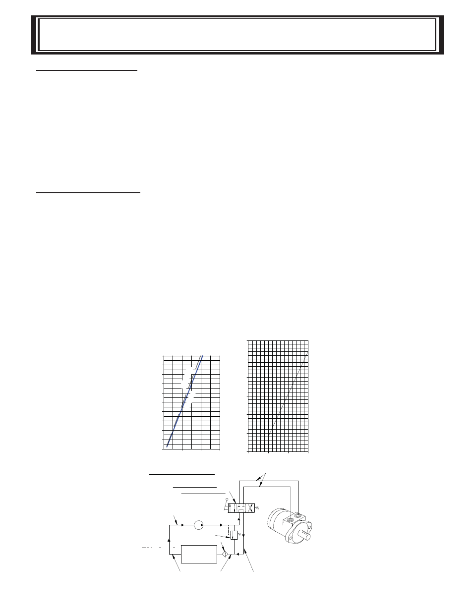
Refer to performance charts, below, to properly match your hydraulic system to the HDG-350
winch performance. The charts consist of:
1. Line pull (lbs.) first layer vs. working pressure (P.S.I.). STATIC refers to lifting a suspended
load from rest; DYNAMIC refers to maintaining the motion of a moving load.
2. Line speed, first layer (F.P.M.) vs. gallons per minute (G.P.M.).
Performance based on a motor displacement of 3.6 cubic inches with 15 GPM maximum flow
rate.
CABLE INSTALLATION
1. Unwind cable by rolling it out along the ground to prevent kinking. Securely wrap end of cable,
opposite hook, with plastic or similar tape to prevent fraying.
2. Insert the end of cable, opposite hook end, into the ½”” dia. hole in drum barrel. Secure
cable to drum barrel, using setscrew furnished with winch. TIGHTEN SETSCREW
SECURELY.
3. Carefully run winch in the “reel-in” direction. Keeping tension on end of cable, spool all the
cable onto the cable drum, taking care to form neatly wrapped layers.
CABLE INSTALLATION / HYDRAULIC SYSTEMS
30
25
20
35
10
15
LINE PULL-FIRST
LA
YER (LB.)
LINE SPEED-FIRST
LA
YER (FPM)
ST
A
TIC
WORKING PRESSURE, PSI
0
1,000
0
1,000
3,000
2,000
5,000
4,000
3,000
2,000
5
HSW-10,000 PERFORMANCE
10,000 LB. DUTY RATING
30:1 GEAR RATIO
7,000
6,000
8,000
FLOW (GPM)
5
0
10
15
WITH 3.6 C.I.D. MOTOR
9,000
10,000
DYNAMIC
PUMP
LOW PRESSURE LINES
RESERVOIR
FLUID
FLUID FILTER
RELIEF VALVE
CONTROL VALVE
EMERGENCY STOP
TYPICAL LAYOUT
3 POSITION 4 WAY
CYLINDER SPOOL
PUMP INLET LINE
(SUCTION)
WINCH MOTOR
HYDRAULIC
(.75 I.D. MINIMUM)
LOW PRESSURE LINES
HIGH PRESSURE LINES
(.50 I.D. MINIMUM)