2 stand mounting, Figure 3-10: vesa compliant stand – IEI Integration UPC-V315-NM70 User Manual
Page 37
UP C-V315-NM70 P a n e l P C
P a g e 26
To install the UPC-V315-NM70 on the arm, follow the directions below.
NOTE:
Make sure the arm supports standard VESA mounting. The
UPC-V315-NM70 uses a VESA mounting to attach to the arm.
S te p 1:
The arm is purchased separately. Follow the instructions in the arm's user
manual to securely attach the arm to the wall.
S te p 2:
Once the mounting arm has been firmly attached to the surface, lift the panel PC
onto the interface pad of the mounting arm.
S te p 3:
Align the retention screw holes on the mounting arm interface with those in the
panel PC. The arm mount retention screw holes are shown in Figure 3-7.
S te p 4:
Secure the flat panel PC to the interface pad by inserting four retention screws
through the bottom of the mounting arm interface pad and into the flat panel PC.
S te p 0:
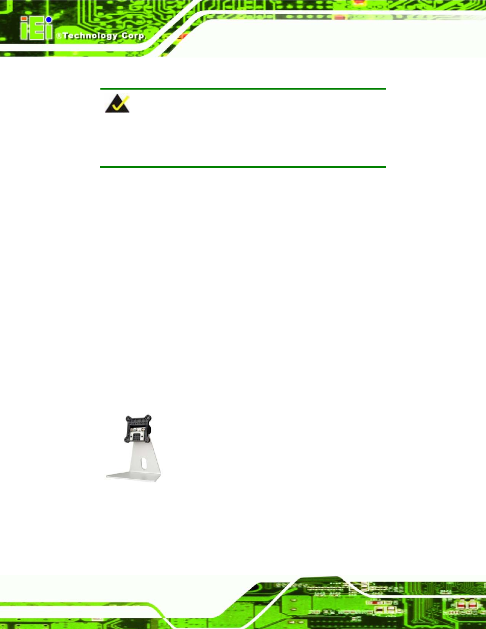
3.6.2 S ta n d Mo u n tin g
The UPC-V315-NM70 can be installed on any stand that supports the standard VESA
mounting interface. An example stand is shown below.
Figure 3-10: VESA Compliant Stand
To install the UPC-V315-NM70 on the stand, follow the directions below.