3 so-dimm installation, So-dimm, Nstallation – IEI Integration ICE-PV-N4551_D5251 User Manual
Page 43: Figure 4-1: so-dimm installation
ICE-PV-N4551_D5251 COM Express Type 2 Module
Page 33
If one or more of these items are missing, please contact the reseller or vendor the
ICE-PV-N4551/D5251 was purchased from and do not proceed any further with the
installation.
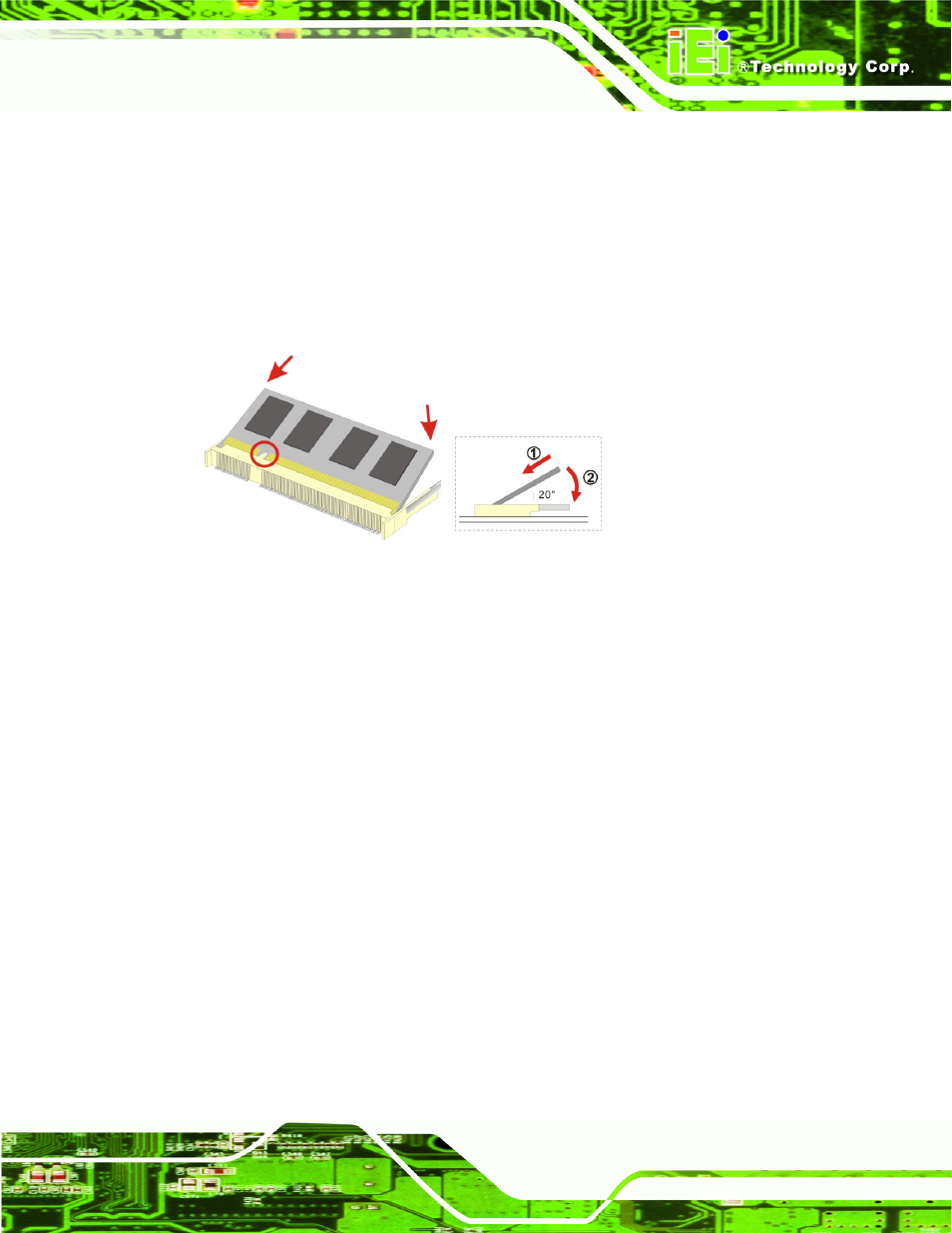
4.3 SO-DIMM Installation
To install a SO-DIMM into a SO-DIMM socket, please follow the steps below and refer to
Figure 4-1: SO-DIMM Installation
Step 1:
Locate the SO-DIMM socket. Place the ICE-PV-N4551/D5251 on an anti-static
pad.
Step 2:
Align the SO-DIMM with the socket. The SO-DIMM must be oriented in such a
way that the notch in the middle of the SO-DIMM must be aligned with the
plastic bridge in the socket.
Step 3:
Insert the SO-DIMM. Push the SO-DIMM chip into the socket at an angle. (See
Step 4:
Open the SO-DIMM socket arms. Gently pull the arms of the SO-DIMM socket
out and push the rear of the SO-DIMM down. (See Figure 4-1)
Step 5:
Secure the SO-DIMM. Release the arms on the SO-DIMM socket. They clip into
place and secure the SO-DIMM in the socket.
Step 0: