2 peripheral interface connectors, Table 4-1: peripheral interface connectors – IEI Integration iQ7-US15W User Manual
Page 40
IQ7 Design Guide
Page 28
4.1.2 Peripheral Interface Connectors
5
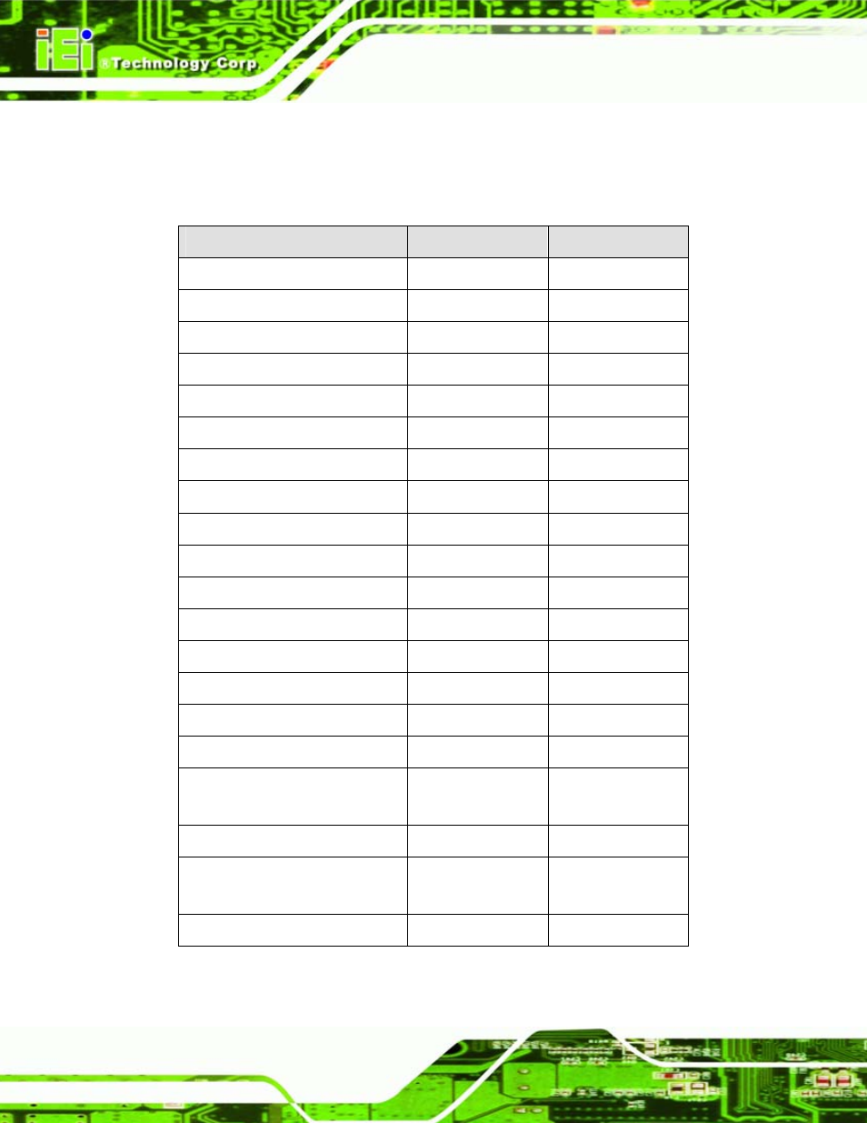
Table 2-1 shows a list of the peripheral interface connectors on the IQ7-DB-MITX.
Detailed descriptions of these connectors can be found below.
Connector
Type
Label
ATX power connector, system
20-pin ATX
PWR1
Backlight inverter connector
5-pin box header
INVERTER1
CompactFlash® connector
CF slot
CF1
Digital I/O
10-pin header
DIO1
Fan connector
3-pin wafer
FAN2
Front panel connector
14-pin header
F_PANEL1
IDE connector
44-pin
CN30
IDE (CPU module to baseboard)
Flat cable
CN6
LVDS connector
30-pin crimp
CN7
LVDS connector
40-pin crimp
CN16
Mini USB port
Mini-USB
USB_CLIENT
PCIe x1 expansion card slot
PCIe x1 slot
PCIE1
PCIe Mini card slot
PCIe Mini
CN2
Power button
Button
SW2
QSeven connector
QSeven
J1
Reset button
Button
SW1
SATA connectors
SATA
S_ATA1, S_ATA2,
S_ATA3
SATA power
4-pin box header
CN17, CN21, CN23
Serial ports
10-pin box header
COM1, COM2,
COM3
USB connector
8-pin header
USB5
Table 4-1: Peripheral Interface Connectors