6 data flow, Figure 3-6: data flow diagram – IEI Integration iQ7-US15W User Manual
Page 35
IQ7 Design Guide
Page 23
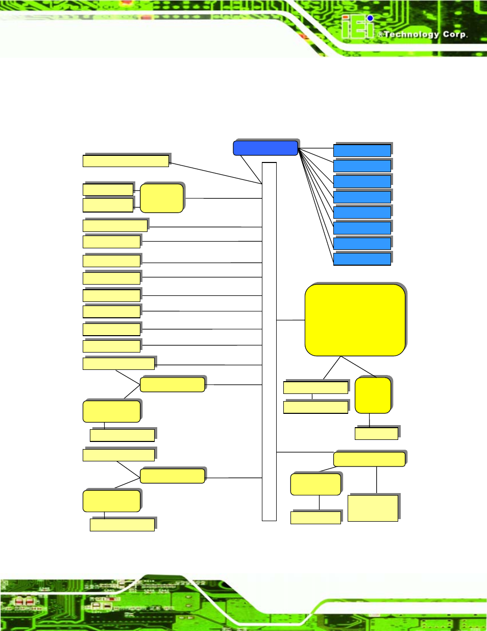
3.6 Data Flow
5
Figure 1-4 shows the data flow between the system chipset, the CPU and other
components installed on the motherboard.
Figure 3-6: Data Flow Diagram
QSeven
Module
USB Client
6 x USB
2 x SATA
SMSC3114
COM1
WDT
PS/2
Digital I/O
LPT
PI2PCIE412-D
HD
Audio
SATA
USB
USB
LPC
I2C
LAN
Realtek
RTL8111CP
Line out
Realtek
ALC888
External Mic
COM2
COM3
COM4
IDE Connector
OR
CompactFlash®
LAN
GbE
PCIe x1
EEPROM
LVDS
Chrontel
CH7308A/B
CRT
SDVO
(Optional)
SD Slot
LVDS
SDVO
SDVO
CRT
QSeve
n Co
n
necto
r
Fan
Smart Fan
PI2PCIE412-D
PCIe Mini Card
USB
Port 80 (Debug)
LAN
Realtek
RTL8111CP
PCIe x1
PI2PCIE412-D
PCIe x1
IDE
-to-
SATA
SATA
OR
OR
This manual is related to the following products: