Warner Electric B30 Single Range Tensioncells User Manual
Page 11
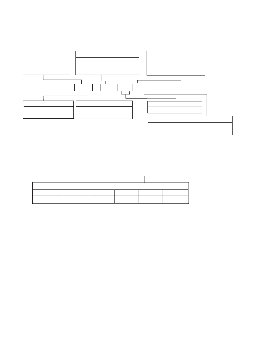
Series Number (2 Digits)
30 Wall Mount
B B 3 0 P 1 6 K W1
Capacity Range
11
Warner Electric • 800-825-9050
P-2012-4 • 819-0404
See Table ll-B
Example Shown:
BC30P16KW1
N = MS Connector
C = Rotating Shaft
30 = Series 30, Wall Mount
P = 0-20 lbs. Capacity
16 = 1” Diameter Shaft
K = K Type DC LVDT
W1 = Split Bushing
Shaft Mounting Configuration
W1-Split bushing
W2-Solid bushing
Electrical
Connection
B - MS Connector
Type
B - Non-Rotating Shaft
See Table II-A
K - DC LVDT with
Maximum 3 VDC Output
Change Including Tare
Displacement
Shaft Diameter
Model Number Nomenclature Example
Series 30, Type B Specifications – Non-Rotating Shaft Mounting
Series 30, Type B – Nominal Capacity Ranges
Code
P
T
U
X
Z
Pounds
0-20
0-50
0-90
0-200
0-500
Note
: Other Load ranges are available on special order. Contact Warner Electric for ratings & abalability.
**Warner Electric wall mounted tensioncells are located by a 5/8-11 bolt at the roll centerline and locating tab which
maintains rotational position of the tensioncell. (See Page 6.)
Notes:
W1 unit shown here.
W2 unit is applied at the opposite end of the roll.
W1 unit clamps the shaft while W2 allows for
temperature expansion of the roll.
Both units have self-aligning feature.
Series 30, Type B Shaft Diameter Code
Code
12
16
20
23
Inches
3/4
1.0
1-1/4
1-7/16
RH
1.00
1.13
Table II-A